The 3 AM Phone Call Every Maintenance Tech Hates
Ask anyone who has worked a night shift in a manufacturing facility about their worst memory, and they will probably tell you a story about a 3 AM line stoppage. The stamping press is frozen, the stack light is blinking red, and thirty workers are waiting around the break room while lost production costs compound by the minute.
Nine times out of ten, the culprit isn't a burned-out motor drive or a fried main processor. It's a tiny $40 sensor on a cylinder bracket that got splashed with cutting fluid and stopped telling the control cabinet that the clamp was closed. A quick wipe with a shop rag, and the line starts moving again.
Sensors are the boots on the ground for industrial control systems. If the central programmable logic controller acts as the brain, sensors serve as the eyes, ears, and touch. Without them, even the most expensive multi-axis robot is completely blind.
When Metal Meets Magnetic Fields: Inductive Sensing
Back in the early days of factory machinery, position checking depended on mechanical limit switches. You had a little metal roller lever that physically bumped into a steel plate as it slid past. Those levers bent, springs snapped, and metal shavings jammed the contacts. Modern shop floors have largely replaced mechanical switches with non-contact proximity sensors.
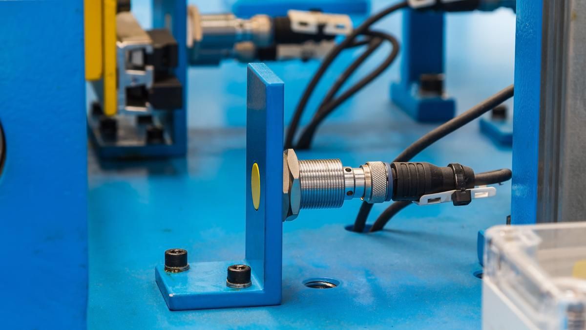
Inductive proximity sensors are the universal choice for detecting metal objects. Inside the sensor barrel, a copper coil generates an alternating electromagnetic field right at the face. When a steel bracket or aluminum block enters that field, tiny electrical currents—called eddy currents—start swirling inside the target metal. These currents draw energy away from the sensor's internal oscillator, causing the circuit amplitude to drop and flipping the output switch.
Here is where many maintenance teams run into trouble during retrofits: inductive sensors do not see all metals equally.
Factory ratings are calibrated using a smooth piece of mild steel. If you swap that steel part out for aluminum, your effective sensing distance drops by nearly 70 percent. Brass cuts the distance in half, and copper reduces it even further. If you try to detect an aluminum automotive bracket with a standard M12 inductive sensor rated for 4 millimeters on steel, the sensor will never trip unless the bracket almost scrapes the lens. In those cases, you either need a larger sensor body or a specialized Factor 1 sensor that uses dual-coil technology to read steel and non-ferrous metals at the exact same distance.
You also need to watch how you mount them. Shielded sensors have a metal collar running all the way to the tip, so you can thread them flush into a steel machine plate without getting a false trip. Unshielded sensors expose the plastic sensing head for a longer range, but if you mount them flush in a metal bracket, the surrounding metal will lock the sensor ON permanently.
Beyond Metal: Reading Liquids, Plastics, and Bulk Solids
When you need to detect non-metallic items like plastic bottles, glass sheets, cardboard boxes, or wood chips, inductive sensors won't help. That is where capacitive sensors take over.
Instead of creating a magnetic field, a capacitive sensor projects an electrostatic field from two concentric metal plates behind its face. As any object—solid or liquid—enters that field, it changes the dielectric constant of the air gap around the tip. The sensor detects this shift in capacitance and triggers its output.
One of the neatest practical uses for capacitive sensing on the shop floor is reading tank levels right through plastic or glass walls. If you mount a capacitive sensor on the outside of a clear PVC sight tube connected to a liquid chemical drum, you can adjust the sensitivity potentiometer until it ignores the thin plastic tube wall and trips only when the liquid level rises inside.
For pneumatic cylinders, you will usually see tiny magnetic sensors clamped directly along the aluminum cylinder housing. These sensors react to a permanent magnetic ring mounted on the internal piston. Old-style reed switches used physical metal blades sealed in glass, but modern setups use solid-state Hall-effect sensors because they have no mechanical contacts to arc or stick under high-speed cycling.
Tracing Movement with Light: Photoelectric Setup Choices
When a target is meters away or moving too fast across a wide conveyor, optical sensors take over. Photoelectric sensors pair a light emitter—typically a red LED, infrared diode, or laser—with a light-sensitive receiver diode.
How you arrange the light path makes a huge difference in reliability:
Through-beam systems split the emitter and receiver into two separate housings mounted directly across from each other. They offer the longest range—sometimes over 20 meters—and punch through airborne dust, steam, and oil mist better than any other optical setup. The trade-off is installation labor, since you have to run power cables to both sides of the machinery.
Retro-reflective models combine the emitter and receiver into one body and point the beam at a corner-cube reflector mounted on the far side. Wiring is faster because everything stays on one side. However, if you are running shiny wrapped pallets or polished stainless steel cans down the conveyor, a standard retro-reflective sensor can get fooled when light bounces straight off the shiny product back into the lens. To fix this, plant engineers use polarized retro-reflective sensors, which fit optical filters so the receiver only accepts light whose angle has been flipped by a real reflector.
Diffuse-reflective sensors bounce light directly off the product itself back into the single sensor body, needing no reflector at all. They are simple to fit in tight spaces, but their range changes depending on target color. A bright white box might trip the sensor from 300 millimeters away, while a matte black rubber tire on the same belt won't reflect enough light until it gets within 50 millimeters.
To avoid color confusion, modern lines use Background Suppression (BGS) sensors. Instead of measuring how much light bounces back, BGS units use optical triangulation to measure the exact return angle of the light beam. If a dark black part passes at 100 millimeters, the returning angle trips the sensor, while a bright white wall 200 millimeters behind it is ignored completely.
Photoelectric technology also forms the backbone of machine safety. Safety light curtains project a array of parallel infrared beams across hazard zones around robot arms and hydraulic presses. If an operator's hand breaks even one beam, redundant safety microprocessors open the circuit and kill power to the servo drives within milliseconds.
Using Sound Waves When Optics Fail
Optical sensors struggle when dealing with clear glass bottles, transparent plastic film, mirrors, or turbulent liquid surfaces where light passes straight through or scatters unpredictably. Ultrasonic sensors bypass light altogether by using high-frequency sound pulses.
An ultrasonic sensor vibrates a piezoelectric ceramic disc tens of thousands of times per second, sending out silent acoustic waves. The sensor listens for the echo bouncing off the target and calculates distance based on time-of-flight. Because sound reflects off physical mass, it doesn't care whether a surface is clear, black, shiny, or dull.
The main thing to watch out for with ultrasonics is the dead zone directly in front of the sensor face. Depending on the frequency, an ultrasonic sensor cannot accurately measure anything closer than 20 to 500 millimeters because the returning echo arrives before the piezoelectric disc stops vibrating from sending the pulse. You always need to mount the sensor far enough back to keep targets out of that dead zone.
Monitoring the Vitals: Temperature, Pressure, and Flow
Beyond tracking part locations, keeping automated machinery healthy requires tracking physical fluid and thermal conditions.
Overheating motor bearings are usually the first sign of mechanical breakdown. Resistance Temperature Detectors—like the common Pt100 sensor—use platinum wire whose electrical resistance rises predictably with heat. They provide exceptionally steady, accurate readings up to 600 degrees Celsius. For extreme heat in forging furnaces or heat-treating ovens, rugged thermocouples take over, generating a small millivolt signal from two welded dissimilar metal wires.
Hydraulic presses and plant air headers depend on pressure transmitters built with flexible stainless-steel or ceramic diaphragms. As fluid pushes against the diaphragm, internal strain gauges convert the movement into an analog 4-20 milliamp current signal. Plant engineers prefer 4-20mA current loops over 0-10 volt signals because current doesn't drop across long factory cable runs, and a complete wire break drops the signal to zero milliamps, immediately triggering a fault alert on the PLC.
For precision motion, rotary encoders attach directly to motor shafts, firing thousands of digital pulses per revolution so drive controllers know exact angular position and speed. When weight matters, alloy-steel load cells sit under hopper legs and conveyor scales, measuring physical metal deflection under heavy loads to ensure precise batch mixing.
The Shift Toward Smart IO-Link Sensors
For decades, standard industrial switches could only tell a controller one basic thing: ON or OFF. If a lens got dirty or a housing overheated, maintenance had no warning until the machine stopped.
The industry is rapidly shifting toward IO-Link communication. Using standard 3-wire sensor cables, IO-Link turns basic sensors into smart digital devices. Instead of just sending a switching signal, an IO-Link sensor continuously reports actual process values, internal operating temperatures, and lens contamination levels back to the control network.
Even better, if a maintenance tech replaces a damaged IO-Link sensor, the master module automatically downloads the original configuration parameters into the new unit as soon as it is plugged in. No manual tuning or screwdriver adjustments required.
A Quick Troubleshooting Guide for Sensor Faults
When an automated machine stops and a sensor status light looks wrong, follow these basic steps before tearing down hardware:
First, look at the status LEDs on the sensor barrel. A solid green light confirms healthy 24V DC power, while yellow indicates an active output signal. If all lights are off, check your power supply fuse or look for a pinched cable line.
Second, wipe the sensing face clean. Coolant mist, oil films, and metallic dust cause more than half of all false trips. A quick wipe with a clean cloth fixes a surprising number of service calls.
Third, verify target alignment and distance. Machine vibration can easily loosen mounting nuts and back a sensor out of its working range.
Fourth, double-check transistor logic. Connecting a PNP (sourcing) sensor to an NPN (sinking) PLC input card means the controller will never register a signal, even if the sensor lights up correctly.
Finally, check your M12 connector caps. Oil seeping into loose cable fittings can short out pins internally. Keeping fittings clean, choosing the right IP protection rating for wet washdown zones, and double-checking wiring logic will keep your automated line running reliably shift after shift.