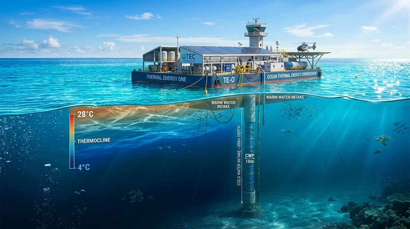
The world's oceans cover approximately 361 million square kilometers of the Earth's surface. Across tropical and equatorial regions, surface waters absorb vast amounts of solar thermal radiation, functioning as an immense natural thermal energy reservoir. Every day, equatorial waters absorb immense amounts of solar thermal energy, maintaining warm surface temperatures of 25°C to 28°C (77°F to 82°F). Meanwhile, deep ocean water—formed in high-latitude polar and sub-polar regions where cold, dense surface water sinks and circulates slowly along the global thermohaline conveyor belt—lies in perpetual darkness 800 to 1,000 meters below at a frigid 4°C to 6°C (39°F to 43°F).
Ocean Thermal Energy Conversion (OTEC) is the marine engineering technology designed to harness this continuous vertical temperature gradient. By operating a low-temperature thermodynamic heat engine between warm surface water and cold deep ocean water, OTEC offers the technical potential to generate clean baseload electricity without consuming fossil fuels or emitting direct operational greenhouse gases.
Unlike weather-dependent renewable energy sources such as solar and wind—which vary with daytime sunlight and wind patterns—OTEC has the inherent capability to generate power around the clock, day and night. However, continuous resource availability should not be confused with guaranteed uninterrupted electricity; actual operational plant availability is subject to scheduled maintenance, biofouling mitigation, and marine weather shutdowns. Despite more than a century of conceptual research and successful small-scale demonstration plants, commercial utility-scale OTEC installations remain rare. Understanding OTEC requires evaluating both its thermodynamic promise and the formidable hydro-engineering, economic, and ecological realities of building multi-megawatt power plants in the open sea.
| Technical Parameter | Closed-Cycle OTEC | Open-Cycle OTEC | Hybrid OTEC |
|---|---|---|---|
| Primary Working Fluid | Pure Anhydrous Ammonia (NH₃) or refrigerant | Warm Seawater (flash-evaporated under vacuum) | Flash steam (water) + secondary ammonia loop |
| Operating ΔT Requirement | Nominally ~20°C (36°F) or more (Useful operation threshold per U.S. EIA; net power depends on plant design and site) |
Nominally ~20°C (36°F) or more (Useful operation threshold per U.S. EIA; net power depends on plant design and site) |
Nominally ~20°C to 22°C or more (Useful operation threshold; net power depends on plant design and site) |
| Gross Thermal Efficiency (Engineering estimates vary by design and operating conditions) |
3.0% to 5.0% (Carnot physical upper bound ~6.7% at ΔT = 20°C; modeled in Dr. Luis Vega 2012 Rankine studies) |
3.0% to 4.5% (Dependent on vacuum flash chamber pressure and intake water temperature) |
3.0% to 4.5% (Combines flash vaporization with secondary vapor loop) |
| Net Electrical Efficiency (After parasitic pump and auxiliary loads) |
2.0% to 3.5% (Baseline closed-cycle Rankine models by Dr. Luis Vega 2012) |
1.5% to 2.5% (Penalized by continuous non-condensable gas vacuum compressor loads) |
1.8% to 2.8% (Intermediate flash-evaporator pinch loss and vacuum pumping) |
| Desalinated Fresh Water | None (requires secondary desalination plant) | Conditional co-production (depends on plant design and vacuum flash fraction; e.g., an illustrative 5.1 MW net open-cycle model by Dr. Luis Vega projected ~2,280 m³/day of distilled water total; requires remineralization and certified treatment before municipal potable use; direct-contact designs yield zero fresh water) | Significant distilled fresh water co-production |
| Turbine Dimensions | Compact vapor turbine (high vapor density) | Massive vacuum steam turbine (low vapor density) | Compact secondary ammonia turbine |
| Current Development Stage | Kilowatt-to-Megawatt operational pilots (TRL 6–7) | Demonstrated pilot prototypes (TRL 6) | Engineering design & specialized research (TRL 5) |
*Technical Comparison Context: Engineering estimates vary by design and operating conditions. The efficiency ranges and technical parameters above represent design-specific model estimates drawn from technical engineering literature (specifically Dr. Luis A. Vega, 2012, "Ocean Thermal Energy Conversion", in Comprehensive Renewable Energy, Vol. 8, pp. 249–263, and historical open-cycle studies), rather than standardized universal benchmarks. While foundational overviews from the U.S. EIA and the IRENA Ocean Thermal Energy Technology Brief outline basic thermodynamic principles, low Carnot conversion limits, and heavy seawater pumping requirements, they do not prescribe universal gross or net efficiency ranges. In practice, actual gross and net efficiencies depend strictly on site-specific ΔT, heat exchanger pinch design, and internal piping friction.
1. What Is Ocean Thermal Energy Conversion?
Ocean Thermal Energy Conversion (OTEC) uses the temperature difference between warm surface seawater and cold deep seawater. The thermocline is the transition zone where ocean temperature changes rapidly with depth, separating warm surface layers from deep oceanic waters.
First conceptualized in 1881 by French physicist Jacques-Arsène d'Arsonval, the fundamental principle rests on classical thermodynamics: whenever a temperature difference exists between two thermal reservoirs, a heat engine can theoretically extract mechanical work by transferring heat from the hot source to the cold sink.
This thermal resource is organized into three distinct ocean layers:
- Surface Layer (0 to 50 m depth): Directly heated by solar radiation, maintaining steady tropical water temperatures between 25°C and 28°C (77°F to 82°F).
- Thermocline Zone (100 to 700 m depth): A rapid transition boundary where water temperature drops steeply with increasing depth as sunlight attenuates.
- Deep Seawater Layer (800 to 1,000+ m depth): Cold, dense deep water circulating through the global ocean (temperature and water-mass origin vary by location, typically 4°C to 6°C / 39°F to 43°F in tropical basins), sustaining the vertical temperature difference necessary to drive thermodynamic power cycles.
The Thermal Resource and the 20°C Temperature Difference
A temperature difference of approximately 20°C (36°F) or more between warm surface water (TH) and deep cold water (TC) is generally considered necessary for practical OTEC operation (as highlighted in technical overviews by the U.S. Energy Information Administration (EIA)). However, actual net power generation and commercial feasibility depend strictly on overall plant design, heat exchanger thermal effectiveness, pumping power requirements, and site-specific seasonal temperature stability.
This thermal gradient generally confines prospective OTEC locations to a tropical belt extending roughly 20 degrees north to 20 degrees south of the equator, where surface waters consistently absorb intense solar irradiance while deep currents maintain near-freezing temperatures at depths around 1,000 meters.
Potential for Continuous Baseload Generation vs. Intermittent Renewables
The defining advantage of OTEC over weather-dependent renewable energy systems is its potential for continuous baseload power generation:
- Continuous Baseload vs. Dispatchability: It is important to distinguish between continuous baseload availability (generating steady, around-the-clock electricity from vast oceanic thermal storage) and dispatchability (the ability to rapidly ramp generation up or down on demand to meet peaking electrical loads). OTEC acts primarily as a continuous baseload resource rather than a fast-ramping peaker plant.
- Continuous Generation Capability vs. Operational Availability: While operational grid-connected solar PV (typically 18%–28% annual fleet capacity factor) and onshore wind (typically 32%–45%) are subject to diurnal and atmospheric intermittency, OTEC possesses the theoretical capability for continuous baseload power generation because oceanic thermal gradients persist day and night. However, actual operational availability is not yet established by commercial-scale operating data. In real-world offshore marine environments, actual availability remains unproven at commercial utility scale and will be governed by scheduled heat exchanger biofouling cleaning, subsea pipeline and mooring inspections, and marine storm shutdowns.
- Grid Stability: Unlike intermittent renewables that require large battery energy storage systems (BESS) or peaker power plants to stabilize frequency and voltage, a continuous baseload OTEC plant supplies steady, predictable power directly to electric grids or isolated island microgrids.
Physical Installation Configurations
Depending on bathymetry (underwater topography) and distance from electrical load centers, OTEC facilities are designed in three primary physical configurations:
- Land-Based Plants: Built directly on coastal shorelines where a steep ocean shelf drops off to 1,000 meters within 1 to 4 kilometers of shore. Seawater is drawn through long submerged pipelines and pumped into onshore machinery. Land-based facilities provide straightforward access for maintenance, avoid heavy marine moorings, and easily export co-products (fresh water, district cooling), but require expensive, long nearshore intake pipes vulnerable to wave action.
- Shelf-Mounted (Nearshore) Platforms: Fixed or bottom-founded jacket structures installed in shallow coastal waters (10 to 50 meters depth) near an underwater cliff. Machinery is elevated above sea level, shortening cold-water pipe runs while avoiding high coastal real estate expenses.
- Floating Offshore Plants: Large semi-submersible platforms, modified oil and gas spar buoys, or ship-shaped Floating Production Storage and Offloading (FPSO) vessels moored in deep water (> 1,000 m). A vertical Cold Water Pipe (CWP) hangs directly beneath the hull. Electricity is transmitted to shore via flexible dynamic submarine power cables, or used onboard to manufacture energy carriers such as green hydrogen, ammonia, or methanol.
Theoretical Potential vs. Proven Operational Reality
Scientific literature, including publications from the International Renewable Energy Agency (IRENA), estimates that tropical oceans absorb enough solar thermal energy to theoretically generate tens of thousands of terawatt-hours (TWh) of electricity annually—far exceeding total global electrical consumption.
However, an essential technical distinction must be maintained between unconstrained theoretical potential and technically and commercially extractable power:
- Extracting power requires pumping billions of cubic meters of seawater without disrupting thermal stratification or inducing oceanographic climate feedbacks.
- As of 2026, operational OTEC installations remain predominantly demonstration pilots and research facilities ranging from 50 kilowatts (kW) to 1 megawatt (MW). No commercial 50 MW to 100 MW utility-scale OTEC plant has operated continuously in the commercial grid market, primarily due to high upfront capital costs, specialized marine component risks, and parasitic pumping requirements.
2. How OTEC Generates Electricity
Ocean Thermal Energy Conversion produces electricity using a specialized adaptation of the Rankine cycle—the same fundamental thermodynamic cycle used in conventional steam power stations, geothermal plants, and modern binary-cycle energy facilities.
However, conventional thermal plants operate across temperature differences of hundreds of degrees Celsius (300°C to 600°C). OTEC operates across an exceptionally small temperature gradient of only 20°C to 24°C. This low temperature difference dictates every aspect of the plant's mechanical and fluid architecture.
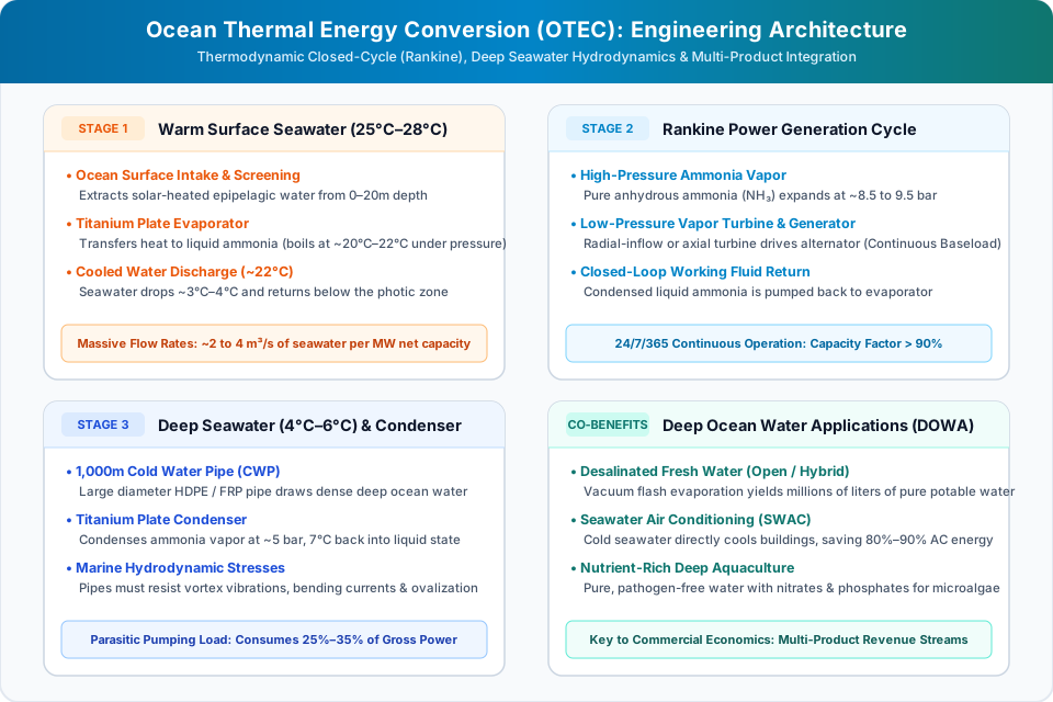
The Closed-Cycle (Rankine) Process Flow
In a standard closed-cycle OTEC system, the power generation process follows four continuous thermodynamic phases:
- Evaporation (Heat Addition at High Pressure):
Warm seawater from the ocean surface (25°C to 28°C) is pumped continuously into a specialized titanium or aluminum plate-and-frame evaporator. Inside the evaporator, heat transfers from the seawater into a low-boiling-point working fluid—most commonly pure anhydrous ammonia (NH₃), which boils at -33.3°C at atmospheric pressure, but is maintained under pressure to boil at approximately 20°C to 22°C inside the heat exchanger. The ammonia absorbs the latent heat of vaporization and transforms entirely into high-pressure vapor at approximately 8.5 to 9.5 bar. - Vapor Expansion (Mechanical Work Generation):
The pressurized ammonia vapor expands through a specialized low-pressure organic vapor turbine. As the gas expands across the turbine blades, thermal and pressure energy are converted into shaft mechanical rotation. The rotating turbine shaft turns a synchronous electromagnetic generator, generating alternating current (AC) electricity. - Condensation (Heat Rejection at Low Pressure):
Having expanded through the turbine and dropped in pressure to approximately 5.0 to 5.5 bar, the cooler ammonia vapor enters a large condenser heat exchanger. Simultaneously, cold seawater pumped from 800 to 1,000 meters depth at 4°C to 6°C circulates through the opposing channels of the condenser. The cold seawater extracts thermal energy from the vapor, condensing the ammonia back into a pressurized liquid state at approximately 7°C to 8°C. - Pressurization (Cycle Closure):
A dedicated liquid feed pump draws the condensed liquid ammonia from the condenser, raises its pressure back to the high-pressure stage (8.5–9.5 bar), and pumps it back into the evaporator. The cycle repeats continuously in a sealed system designed as a closed loop to contain the working fluid; however, operational leakage remains possible and requires ongoing monitoring and containment systems.
3. Closed-Cycle vs. Open-Cycle vs. Hybrid OTEC
Thermodynamic engineers have developed three distinct system architectures for ocean thermal energy conversion, each presenting distinct mechanical complexities, equipment sizes, and secondary product outputs.
The fundamental distinction across these thermodynamic configurations lies in how the working fluid is handled:
- Closed-Cycle Systems: Circulate a secondary low-boiling-point fluid (such as anhydrous ammonia) in an isolated loop through an evaporator, turbine, condenser, and feed pump.
- Open-Cycle Systems: Flash-evaporate warm surface seawater under vacuum to produce low-pressure steam that drives a large-diameter turbine and condenses into distilled fresh water.
- Hybrid Systems: Use warm seawater flash-steam to vaporize ammonia in a secondary closed loop, simultaneously co-producing high-volume fresh drinking water and driving a compact turbine.
1. Closed-Cycle OTEC (Anderson Cycle)
Closed-cycle systems utilize an isolated secondary working fluid circulated inside a sealed loop.
- Working Fluids: Pure anhydrous ammonia (NH₃) is the industry standard due to its high latent heat of vaporization, favorable transport properties, and manageable saturation pressures at ambient temperatures. Fluorocarbon refrigerants (such as R-134a or newer low-GWP hydrofluoroolefins) and hydrocarbons (such as propane) have been evaluated, but ammonia remains preferred for its thermal performance. Advanced cycles like the Kalina cycle (a varying mixture of water and ammonia) have been deployed in experimental facilities (such as Saga University in Japan) to enhance thermodynamic efficiency by matching boiling temperatures across heat exchangers.
- Turbine Scale: Because ammonia vapor has a high density at operating pressures (~6 to 7 kg/m³), closed-cycle turbines are relatively compact. A multi-megawatt ammonia turbine resembles a standard industrial refrigerant expansion turbine, with moderate rotor dimensions relative to its power capacity.
- Advantages: Compact machinery, high volumetric power density, mature industrial component availability, and proven operational history in demonstration plants.
- Disadvantages: Uses toxic/flammable ammonia requiring double-walled containment and gas-detection safety systems; requires very large, expensive titanium plate heat exchangers; produces zero fresh water as a direct byproduct.
2. Open-Cycle OTEC (Claude Cycle)
First demonstrated in Cuba in 1930 by French inventor Georges Claude, open-cycle OTEC uses the ocean water itself as the working fluid, completely eliminating secondary chemical working fluids.
- Flash Evaporation Process: Warm surface seawater (25°C to 28°C) is pumped into an evacuated vacuum chamber maintained at approximately 0.03 bar (3 kilopascals / 0.44 psi)—a pressure below the saturation vapor pressure of water at that temperature. At this low pressure, a small fraction (typically 0.5% to 1.0%) of the warm seawater spontaneously boils into low-temperature steam without adding external heat.
- Desalination and Distilled Water Generation: When seawater flash-boils, dissolved salts, minerals, and heavy metals remain behind in the brine pool. If the resulting steam is condensed against cold deep seawater using a surface heat exchanger (rather than direct-contact mixing), it condenses into pure, high-grade demineralized distilled water. In open-cycle design models analyzed by ocean thermal researchers (for example, an illustrative 5.1 MW net plant configuration modeled by Dr. Luis Vega), freshwater yields on the order of approximately 2,280 cubic meters (~2.28 million liters) per day were projected for the overall facility under a continuous temperature gradient (ΔT ≥ 20°C). However, actual freshwater yield is highly dependent on the specific cycle flash-evaporation fraction, surface condenser capacity, and intake water flow rates, while open-cycle systems using direct-contact condensers (where cold seawater mixes directly with steam) produce zero fresh water. Importantly, because distilled water lacks essential dissolved minerals, post-treatment mineral adjustment (remineralization with calcium and magnesium) and certified water-quality testing compliant with local drinking water standards (such as WHO guidelines or BIS IS 10500) are required before it can be distributed as potable municipal tap water.
- The Low-Density Steam Challenge: At 0.03 bar, water vapor has an exceptionally low density (~0.025 kg/m³), occupying several hundred times the volume of standard atmospheric steam. To produce significant mechanical power, the steam must pass through a colossal, low-pressure turbine. In open-cycle engineering design studies (such as those evaluated in NREL and early Claude cycle literature), even a multi-hundred-kilowatt or 1 MW low-pressure turbine requires disproportionately massive rotor spans and extensive flow cross-sections operating inside deep vacuum, creating significant manufacturing and casing cost challenges.
- Vacuum and Deaeration Penalties: Seawater naturally contains dissolved gases (nitrogen, oxygen, carbon dioxide). Inside the vacuum chamber, these gases instantly desorb, threatening to collapse the vacuum. Large vacuum compressors must run continuously to purge non-condensable gases, imposing substantial parasitic electrical consumption.
3. Hybrid OTEC Systems
Hybrid systems seek to combine the fresh water generation of open-cycle systems with the compact turbine mechanics of closed-cycle systems:
- Warm seawater is flash-evaporated in a low-pressure vacuum chamber to produce pure low-pressure steam.
- Rather than driving a massive low-density steam turbine, the steam is directed into a heat exchanger where it condenses, transferring its heat to boil liquid ammonia in a secondary closed Rankine cycle.
- The condensed steam yields fresh potable water, while the high-density ammonia vapor drives a compact, high-efficiency turbine.
- While thermodynamically elegant, hybrid systems add system complexity, requiring both vacuum flash equipment and chemical working-fluid safety systems.
4. Why OTEC Has Low Net Efficiency
One of the most widely misunderstood aspects of OTEC is its thermal efficiency. Critics often highlight that OTEC plants achieve gross thermal efficiencies of only 3% to 5%, with net electrical efficiencies dropping to 2.0% to 3.5%. Understanding the physics behind these numbers explains why low efficiency is an inherent thermodynamic reality—and why it does not invalidate OTEC's economic viability.
The Carnot Limit
The maximum possible theoretical efficiency of any heat engine operating between a hot reservoir (TH) and a cold reservoir (TC) is dictated by the Carnot efficiency formula, where temperatures are expressed in absolute Kelvin:
Consider typical tropical ocean parameters:
- Warm Surface Water (TH): 25°C = 298.15 K
- Cold Deep Seawater (TC): 5°C = 278.15 K
The absolute physical upper bound for converting heat into work across these ocean temperatures is only 6.71%.
Practical Gross Thermal Efficiency
In a real-world Rankine cycle, practical thermodynamics further reduce this value:
- Heat Exchanger Temperature Pinches: Heat cannot transfer across an evaporator or condenser with zero temperature difference. In practice, a temperature drop of 2°C to 3°C is required across both the evaporator and condenser. This reduces the effective working-fluid temperature differential from 20°C down to roughly 14°C to 16°C.
- Turbine and Generator Inefficiencies: Real vapor turbines achieve isentropic efficiencies of 80% to 88%, and electrical alternators operate at 95% to 97% efficiency.
- Consequently, engineering estimates vary by design and operating conditions; in baseline closed-cycle Rankine design models (such as those analyzed by Dr. Luis A. Vega, 2012, Comprehensive Renewable Energy, Vol. 8, pp. 249–263), an engineered closed-cycle OTEC system achieves an estimated gross thermal efficiency of 3.0% to 5.0% across a typical 20°C to 22°C gradient. Foundational overviews by the U.S. Energy Information Administration (EIA) and IRENA describe the core thermodynamic principles and low Carnot limits without standardizing a single universal operational efficiency range.
The Parasitic Pumping Load Penalty
To generate meaningful amounts of electricity from a cycle operating at 3% to 5% gross efficiency, immense volumetric quantities of seawater must be pumped continuously:
- In baseline closed-cycle Rankine design models (such as those analyzed by Dr. Luis Vega in Comprehensive Renewable Energy, 2012, and IRENA technical assessments), an OTEC plant operating across a nominal surface-to-deep temperature differential of ΔT ≈ 20°C to 22°C requires approximately 2.0 to 3.0 m³/s of warm surface seawater and 1.5 to 2.5 m³/s of cold deep seawater per net megawatt of electric capacity.
- Combining both intake streams yields an estimated total seawater circulation of approximately 3.5 to 5.5 m³/s per net megawatt.
- Under these specific thermodynamic assumptions (warm intake at ~26°C, cold intake at ~4.5°C, and gross-to-net power ratio of ~65% to 70%), an illustrative 10 MW net plant design requires a combined seawater throughput on the order of 35 to 55 cubic meters per second (35,000 to 55,000 liters/second). This figure is an illustrative design estimate rather than a rigid universal engineering requirement: actual required volumetric throughput scales with site-specific ΔT, heat exchanger heat-transfer coefficients, allowable channel velocities, and permissible friction head losses.
Importantly, in a floating or submerged marine system, the pump is not lifting water against 800 to 1,000 meters of static gravity head, because ambient ocean hydrostatic pressure naturally balances the submerged fluid column. Instead, pumping power depends on pipe wall friction, flow rate, intake and discharge losses, fluid density variations between cold deep water and warm surface water (density difference Δρ), and the system’s hydraulic configuration. In baseline closed-cycle Rankine design models analyzed by Dr. Luis A. Vega (2012, Comprehensive Renewable Energy, Vol. 8), total dynamic friction head losses are estimated at approximately 3 to 6 meters of water equivalent head under specific assumptions (smooth conduit wall friction, fluid velocities of ~2 m/s, and low-loss plate heat exchangers). However, because volumetric flow rates are so colossal, even this modest dynamic head loss translates into megawatts of parasitic electrical consumption. Under Dr. Vega's baseline modeling framework, parasitic pumping loads typically absorb an estimated 25% to 40% of gross mechanical turbine generation:
- Cold-Water Pumping: Consumes an estimated 18% to 25% of gross generator output in this specific baseline model to overcome conduit wall friction, inlet screen resistance, density head differences, and plate condenser flow channels.
- Warm-Water Circulation: Consumes roughly 10% to 15% of gross generator output to circulate high volumetric flows through evaporator channels.
- Auxiliary Systems & Working Fluid Pumps: Consume 2% to 4% for feed pumps, vacuum exhausters, and plant controls.
- Net Usable Power Delivered to the Grid: Leaves approximately 60% to 75% of gross generation, yielding a modeled net electrical plant efficiency of 2.0% to 3.5% (gross Rankine thermal efficiency minus parasitic loads, as modeled in Dr. Luis Vega's baseline technical chapter, 2012; engineering estimates vary by design and operating conditions, with IRENA describing the overarching parasitic pumping challenges rather than prescribing a single universal net efficiency range).
(Note: These specific seawater flow rates [3.5–5.5 m³/s per net MW], dynamic head values [3–6 m], and parasitic pumping allocations [25%–40%] are illustrative engineering estimates derived from Dr. Luis A. Vega's baseline closed-cycle modeling framework [2012, Comprehensive Renewable Energy, Vol. 8, pp. 249–263] under idealized conduit and heat-exchanger assumptions. They are not universal physical rules; actual fluid circulation, friction head losses, and net power outputs vary substantially across different plant scales, conduit diameters, and heat exchanger hydraulic geometries.)
Why Low Efficiency Is Not a Showstopper
In a coal, gas, or nuclear power plant, low thermal efficiency is disastrous because fuel costs money; low efficiency burns more fuel and emits more pollution per kilowatt-hour.
In OTEC, the thermal fuel (solar-heated ocean surface water) is free, continuous, and inexhaustible. Low efficiency does not increase fuel expenses. However, low efficiency does mean that capital equipment must be enormous: heat exchangers, water intake structures, and pumps must be exceptionally large per megawatt of net generation, directly driving up initial capital expenditures (CapEx).
5. Deep-Seawater Pipes, Pumps and Heat Exchangers
The commercial realization of OTEC depends entirely on resolving three core mechanical and civil engineering subsystems: the deep Cold Water Pipe, high-volume seawater pumping equipment, and ultra-high-efficiency marine heat exchangers.
1. The Cold Water Pipe (CWP): Engineering in the Ocean Abyss
The Cold Water Pipe is widely regarded by ocean engineers as the single most demanding technical component of an OTEC installation:
- Physical Scale: To reach dense 4°C water, the CWP must descend 800 to 1,000 meters (2,600 to 3,300 feet) vertically from a floating hull or along a steep underwater shelf. Preliminary hydrodynamic sizing models (such as those compiled by IRENA and Dr. Luis Vega) estimate that an indicative 10 MW pilot plant requires a cold-water conduit diameter on the order of 3 to 4 meters, while commercial 50 MW to 100 MW concepts evaluate conduit diameters spanning 6 to 10 meters, depending on target fluid velocities and permissible friction head losses.
- Material Selection: Steel is too heavy, causing catastrophic tensile strain at the hull connection. Modern CWP designs utilize High-Density Polyethylene (HDPE) for smaller demonstration diameters (< 2 m), and Fiberglass-Reinforced Polymer (FRP), syntactic foam-insulated composites, or elastomer-segmented joints for large utility-scale systems.
- Hydrodynamic Stresses:
- Vortex-Induced Vibration (VIV): Cross-currents moving past a 1,000-meter vertical cylinder shed alternating vortices, inducing severe harmonic vibrations that can cause structural fatigue failure within months if unmitigated. Engineers apply helical strakes or aerodynamic fairings to suppress vortex shedding.
- Deep Current Shear: Ocean currents move at different velocities and directions at different depths (e.g., strong eastward surface current vs. sluggish westward intermediate current), creating severe bending moments along the pipe length.
- Internal Suction Negative Pressure: As high-discharge pumps draw tens of thousands of liters of seawater per second upward (e.g., an illustrative ~35,000 to 55,000 liters/second for a 10 MW plant), the internal fluid pressure drops below ambient ocean hydrostatic pressure. If wall thickness or hoop stiffness is inadequate, the pipe will suffer catastrophic ovalization and buckling collapse.
2. High-Efficiency Marine Heat Exchangers
Because the driving temperature difference across heat exchangers is only 2°C to 3°C, heat transfer must be optimized to the physical limits:
- Surface Area Requirements: A 10 MW OTEC plant requires tens of thousands of square meters of heat transfer surface area.
- Materials: Seawater is an aggressive electrolyte. Heat exchangers must resist uniform corrosion, chloride pitting, and crevice corrosion over a targeted multi-decade design life (typically 25 to 30 years under offshore marine standards). Titanium (ASTM Grade 2) is the primary material used in demonstration plants due to its near-zero corrosion rate in seawater. However, titanium is expensive. Advanced research focuses on specialized roll-bonded aluminum alloys with protective coatings, though long-term marine durability remains a subject of ongoing validation.
- Biofouling Mitigation: Warm surface seawater is rich in marine microorganisms, algae, and barnacle larvae. Without mitigation, marine microfouling literature indicates that microbial slime layers can significantly impair overall heat transfer coefficients—with reductions of 20% to over 40% documented in uncleaned seawater test loops. Mitigation strategies include periodic mechanical brushing (sponge ball flushing), low-concentration electrolytic chlorination (< 0.1 ppm), or pulsed ultrasonic transducers. In contrast, cold deep seawater generally has different and often lower biological activity than surface water (with microbial content varying by location and depth), causing substantially less macro-fouling inside condensers.
3. Colossal Low-Head Axial-Flow Pumps
OTEC does not require high-pressure water delivery; because ambient ocean hydrostatic pressure balances the submerged fluid column, high-pressure lifting is not required. Instead, pumping power depends on pipe friction, flow rate, intake and discharge losses, fluid density variations, and the system’s hydraulic configuration (typically resulting in a low total dynamic head of 3 to 6 meters):
- Systems deploy specialized low-speed axial-flow and mixed-flow propeller pumps.
- Pump impellers measure 2 to 4 meters in diameter, fabricated from nickel-aluminum bronze (NAB) or super-duplex stainless steel to withstand cavitation, erosion-corrosion, and structural fatigue during decades of continuous submerged operation.
6. Potential Applications Beyond Electricity
Because OTEC pumps enormous volumes of pristine, cold, nutrient-rich deep seawater with significantly lower organic and bacterial burdens than surface water, an installation can function as the core of an integrated multi-industry marine industrial park. These secondary applications—collectively known as Deep Ocean Water Applications (DOWA)—dramatically improve overall project economics.
This integrated multi-product model routes deep seawater through cascading thermal and biological applications:
- Primary Power Generation: Deep water (4°C to 6°C) condenses working fluid vapor to sustain continuous baseload grid electricity.
- Direct District Cooling (SWAC): Chilled seawater can substantially reduce electrical air-conditioning chiller loads in coastal buildings.
- Fresh Water Co-Production: Vacuum distillation can co-produce substantial quantities of distilled water for coastal communities (subject to post-treatment remineralization).
- Nutrient-Rich Mariculture & Agriculture: Effluent water containing high concentrations of nitrates, phosphates, and pure trace minerals nourishes microalgae (spirulina), cold-water aquaculture, and subsurface soil-cooled crop farming.
1. Seawater Air Conditioning (SWAC)
In tropical islands and coastal cities, electrical air conditioning typically consumes 40% to 60% of total commercial building electricity.
- The SWAC Mechanism: Instead of running energy-intensive compressor chillers, cold deep seawater at 5°C is pumped directly through closed-loop plate heat exchangers. The seawater chills freshwater circulated through district cooling networks servicing hotels, airports, hospitals, and commercial buildings.
- Energy Savings: SWAC systems eliminate the energy-intensive mechanical refrigeration compressor, consuming electricity primarily for seawater intake and distribution pumps. In operational facility studies and district cooling assessments (such as evaluations by UNEP and facility data at NELHA), SWAC installations demonstrate large cooling-related electrical reductions compared to standard vapor-compression chillers; however, net energy savings are strictly site-dependent and governed by seawater intake temperatures, auxiliary distribution pumping power, heat exchanger effectiveness, and the baseline chiller Coefficient of Performance (COP).
- Operational Precedents: Notable operational seawater air-conditioning systems include the resort cooling facility at the InterContinental Bora Bora Resort & Thalasso Spa in French Polynesia (commissioned in 2006 using 900-meter-deep seawater) and ongoing seawater cooling research and commercial applications at the Natural Energy Laboratory of Hawaii Authority (NELHA) in Kona, Hawaii. While other large municipal SWAC projects (such as proposed commercial networks in Honolulu or Nassau, Bahamas) have been designed and evaluated, high upfront capital pipeline costs and marine permitting remain major development hurdles.
2. High-Purity Fresh Water Desalination
Small tropical island developing states (SIDS) suffer chronic freshwater shortages, relying on diesel-powered reverse osmosis (RO) desalination or erratic rainfall:
- As detailed in open-cycle and hybrid configurations, flash-evaporating warm surface water in a vacuum chamber and condensing it against cold deep seawater produces high-purity distilled water.
- To convert this distilled condensate into safe municipal drinking water, treatment facilities perform mineral adjustment (adding beneficial calcium and magnesium ions) and rigorous water-quality testing to ensure compliance with potable water regulations.
- Unlike reverse osmosis—which consumes substantial electricity (~3.5 to 4.5 kWh/m³) and discharges concentrated chemical-laden brine—open-cycle OTEC co-produces fresh water as an integral thermodynamic feature of low-temperature vacuum condensation.
3. Nutrient-Rich Deep Ocean Aquaculture (Mariculture)
Surface ocean waters in tropical latitudes are naturally nutrient-depleted (oligotrophic) because phytoplankton rapidly consume nitrates and phosphates in the sunlit zone. In contrast, deep ocean water at 1,000 meters contains elevated nutrient reserves:
- Nutrient Density: In many tropical oceanic basins, deep ocean water contains substantially higher concentrations of dissolved inorganic nutrients (nitrates NO₃⁻, phosphates PO₄³⁻, and silicates SiO₂) than sunlit, biologically depleted surface waters. However, exact concentration ratios and chemical profiles vary considerably across different oceanic basins, water depths, and seasonal upwelling patterns, requiring site-specific oceanographic sampling.
- Biological Characteristics: Having spent centuries isolated in dark ocean depths away from terrestrial runoff and solar penetration, deep ocean water generally contains far lower concentrations of surface organic contaminants and common human pathogens than coastal waters, although local microbial ecology varies by geographic location and depth.
- Cultivation Success: Specialized research and commercial mariculture facilities (such as the Natural Energy Laboratory of Hawaii Authority - NELHA) have utilized deep seawater effluent to culture spirulina microalgae, abalone, Atlantic salmon (grown in tropical Hawaii due to chilled water), and sea asparagus.
4. Cold-Soil Agriculture (Experimental Research Applications)
By running cold deep seawater through shallow subterranean plastic pipes buried beneath agricultural fields, researchers have demonstrated root-zone cooling in tropical microclimates:
- The chilled soil cools plant roots and condenses ambient air humidity directly at ground level, creating localized micro-irrigation.
- In experimental research trials at NELHA and academic pilot plots, this technique enabled temperate agricultural crops—such as strawberries, lettuces, and brassicas—to grow in hot tropical coastal settings where they would otherwise suffer heat stress. However, commercial scalability remains subject to pipe installation costs, soil salinity monitoring, and condensation management.
7. Installation Costs and Commercial Limitations
Despite its compelling physical advantages, OTEC has struggled for decades to transition from small experimental facilities to commercial utility-scale deployment. A realistic technical appraisal must evaluate the financial, mechanical, and logistical barriers that constrain commercialization.
| Generation Technology & Capacity | Source / Study & Year | Estimated CapEx ($/kW) | Estimated LCOE ($/kWh) | Key Assumptions & Operational Profile |
|---|---|---|---|---|
| Utility-Scale Solar PV | IRENA / IEA Empirical Data (2023–2024) | $800 – $1,200 / kW | $0.03 – $0.06 / kWh | Commercial empirical data; intermittent daytime generation (18%–28% fleet capacity factor) |
| Onshore Wind | IRENA / IEA Empirical Data (2023–2024) | $1,200 – $1,800 / kW | $0.03 – $0.07 / kWh | Commercial empirical data; variable wind-dependent generation (32%–45% fleet capacity factor) |
| Offshore Wind (Fixed-Bottom) | IRENA / IEA Empirical Data (2023–2024) | $2,800 – $4,500 / kW | $0.07 – $0.12 / kWh | Commercial empirical marine data; variable generation (42%–55% fleet capacity factor) |
| Small Demonstration Pilot OTEC (1–1.35 MW) | IRENA (2014) reviewing pilot studies (e.g., Vega 2010) | ~$16,400 – $35,400 / kW (Model projection) |
~$0.51 – $0.94 / kWh (Model projection) |
First-of-a-kind pilot units; high engineering contingency; no scale economies; continuous generation capability, but commercial availability unverified |
| Pre-Commercial Island OTEC (~10 MW) | IRENA (2014) / Dr. Luis Vega (2012) | ~$16,400 – $35,400 / kW (Model projection) |
~$0.20 – $0.45+ / kWh (Model projection) |
Pre-commercial island plant models; sensitive to financing terms and whether co-products (fresh water, district cooling) offset power costs; commercial availability unverified |
| Projected Commercial OTEC (50–100 MW) | IRENA (2014) multi-MW engineering literature | ~$5,000 – $15,000 / kW (Model projection) |
$0.10 – $0.25 / kWh (Model projection) |
Floating commercial concepts (Nth-of-a-kind); assumes mature composite CWP supply chains and economies of scale; unbuilt and unproven at utility scale |
*Cost & Performance Benchmarking Context: Capital expenditure and LCOE estimates for OTEC represent theoretical, model-based feasibility projections compiled across different engineering studies and synthesized in the International Renewable Energy Agency's technology brief (IRENA, Ocean Energy Technology Brief, published in 2014) and related techno-economic literature (e.g., Dr. Luis Vega, 2012). In its assessment, IRENA emphasizes that available cost figures for OTEC vary substantially by plant capacity and are constrained because utility-scale commercial plants (50–100 MW) have not yet been built. Small demonstration pilots (1–1.35 MW) incur high prototype fabrication expenses leading to modeled LCOEs of $0.51–$0.94/kWh, whereas pre-commercial 10 MW island designs project $0.20–$0.45+/kWh, and 50–100 MW utility concepts extrapolate $0.10–$0.25/kWh based on anticipated economies of scale. Furthermore, direct comparisons between solar PV, wind, and OTEC are strictly indicative: each technology operates under fundamentally different geographic constraints, financing terms, and grid connection requirements. While OTEC possesses the theoretical capability for continuous baseload power due to ocean thermal storage, actual operational availability is not yet established by commercial-scale operating data, as offshore facilities remain subject to biofouling cleaning, pipeline inspections, and severe weather shutdowns.
1. High Initial Capital Expenditure (CapEx)
Because OTEC operates across a narrow temperature gradient, its thermodynamic machinery must be extraordinarily large:
- High-grade titanium heat exchangers with massive surface areas represent 25% to 35% of total plant capital costs.
- Fabricating, transporting, and submerging a 1,000-meter-long, multi-meter-diameter pipe in open-ocean conditions requires specialized marine construction vessels, diving teams, and deepwater robotics.
- For small demonstration plants (1 MW to 10 MW), turnkey capital expenditures are projected at $16,400 to $35,400 per kilowatt ($16.4M to $35.4M per MW) in IRENA's 2014 baseline techno-economic review. While scaling up to commercial 50 MW to 100 MW installations is projected in engineering models to lower unit costs to $5,000–$15,000/kW through economies of scale, securing private capital without sovereign loan guarantees remains a critical commercial barrier.
2. High Levelized Cost of Electricity (LCOE)
Due to substantial upfront capital amortization and ongoing marine operations and maintenance (O&M), LCOE varies significantly across plant capacity and study assumptions:
- Small Demonstration Pilots (1–1.35 MW): Early techno-economic reviews summarized in IRENA (2014) report high LCOEs of $0.51 to $0.94 per kWh, driven by first-of-a-kind prototype fabrication and the absence of economies of scale.
- Pre-Commercial Island Facilities (~10 MW): Engineering models (such as Vega, 2012, and IRENA, 2014) project LCOEs on the order of $0.20 to $0.45+ per kWh, depending heavily on cost of capital and whether co-products like desalinated fresh water or SWAC provide revenue offsets.
- Projected Commercial Utility Plants (50–100 MW): Engineering models extrapolate lower potential LCOEs of $0.10 to $0.25 per kWh, though these figures remain unverified projections since no utility-scale plant has ever been constructed.
- On major continental grids connected to cheap natural gas, utility solar, or onshore wind, standalone OTEC cannot compete on raw electricity cost alone.
- The Island Economic Context: On isolated tropical islands (such as Tuvalu, Kiribati, remote Caribbean islands, or isolated archipelagos), electricity is generated primarily using imported diesel fuel transported by sea tankers. While domestic consumer billing tariffs are often subsidized by regional governments, the underlying unsubsidized utility cost of diesel power generation commonly exceeds $0.30 to $0.50+ per kWh. In these diesel-reliant island microgrids—particularly where power is co-generated alongside fresh water and air-conditioning offsets—techno-economic models suggest that OTEC could theoretically approach competitive parity; however, this remains an unproven commercial proposition dependent on securing high-risk financing, reducing high installation expenses, and demonstrating long-term marine operating reliability.
3. Technological Readiness Levels (TRL)
- Kilowatt-Scale & Component Research (TRL 7–8): Operational demonstration installations—such as the 100 kW facility on Kume Island (Kumejima), Okinawa, Japan (commissioned in 2013 on the grounds of the Okinawa Prefecture Deep Sea Water Research Center by Saga University and industrial partners, operating with two 50 kW units) and Makai Ocean Engineering's 105 kW demonstration facility in Hawaii—have successfully validated closed-cycle Rankine thermodynamics, automated control systems, and long-term marine heat exchanger durability.
- Utility-Scale Systems (TRL 4–5): A commercial 50 MW to 100 MW offshore floating facility requires deploying a 6-to-10-meter diameter CWP and high-capacity dynamic subsea transmission cables in open ocean waters. No engineering consortium has yet completed this transition, due to the high financial risk of structural failure during construction or storm events.
4. Marine Operating Hazards
- Typhoons and Tropical Cyclones: Floating OTEC installations in the Western Pacific or Bay of Bengal must withstand Category 5 super-typhoons, experiencing wave heights exceeding 15 meters and intense lateral wind loads. Mooring lines and flexible umbilical cables must endure these multi-axis dynamic loads without snapping.
- Atmospheric & Marine Corrosion: Operating high-voltage power generation equipment in a perpetual salt-fog atmosphere requires hermetically sealed enclosures, cathodic sacrificial protection, and specialized marine coatings.
8. Environmental Impacts and Marine Ecosystems
Like any large-scale industrial intervention in the natural environment, OTEC is not without ecological consequences. Siting and operating an OTEC power plant demands rigorous Environmental Impact Assessments (EIA) to evaluate its interaction with pelagic and deep-sea marine ecosystems.
Environmental assessments evaluate four primary oceanographic interactions:
- Surface Water Intake: Risk of entraining fish eggs, larvae, and plankton; mitigated by large intake cross-sections evaluated during site-specific environmental assessments to maintain low approach velocities (such as ~0.15 m/s, drawing by analogy on coastal cooling intake engineering precedents).
- Discharge Plume Dynamics: Risk of nutrient-rich deep water triggering artificial algal blooms in sunlit surface zones; mitigated by evaluating subsurface discharge below the seasonal photic zone in site-specific hydrodynamic plume modeling.
- Temperature Plume Modification: Potential localized thermal plume alterations evaluated in hydrodynamic simulations to optimize multi-port diffuser mixing and ensure neutral buoyancy.
- Dissolved Gas Dynamics: Dissolved inorganic gas release during open-cycle vacuum flash evaporation, evaluated under model-specific operating assumptions (e.g., Green & Guenther 1990).
1. Deep Nutrient Upwelling and Eutrophication Risks
Deep seawater is rich in nitrates and phosphates. If an OTEC facility discharges this cold, nutrient-rich water directly into the warm, sunlit photic zone (the top 50 to 80 meters where sunlight penetrates), it introduces artificial upwelling:
- Eutrophication: Sudden influxes of concentrated marine nutrients into oligotrophic tropical surface waters can stimulate rapid, uncontrolled phytoplankton blooms.
- Harmful Algal Blooms (HABs) as a Potential Ecological Risk: In environmental impact reviews, the stimulation of harmful algal blooms (HABs) or red tides is evaluated as a potential ecological risk if nutrient-rich deep water were to be discharged directly into the sunlit photic zone without dilution. It represents an evaluated design risk in environmental planning rather than a demonstrated effect of any specific operating OTEC facility.
- Engineering Mitigation: Rather than releasing effluent at the surface, environmental engineering frameworks evaluate deep subsurface discharge as a site-specific design option in hydrodynamic plume modeling to place effluent beneath the local seasonal thermocline and primary photic zone. Siting and discharge depth are strictly site-specific: local oceanographic currents, ambient stratification, and bathymetry determine the optimal depth to prevent surface algal stimulation and allow natural oceanic dissipation.
2. Organism Entrainment and Impingement
Drawing high volumetric throughputs of seawater requires careful hydraulic engineering to avoid harming marine life:
- Impingement: Larger marine life (adult fish, sea turtles, marine mammals) being physically pinned against intake trash racks by water suction.
- Entrainment: Microscopic marine organisms (fish larvae, coral spawn, crab zoeae, phytoplankton) being drawn through intake screens, passing through pumps and heat exchangers, and experiencing thermal and pressure shock.
- Engineering Mitigation: Intake structures are engineered with extraordinarily large cross-sectional surface areas to maintain low intake velocities (often evaluated around 0.15 meters per second / 0.5 ft/s during site-specific marine environmental assessments, drawing by analogy on established cooling water intake literature like U.S. EPA Clean Water Act Section 316(b), although EPA rules are not a direct statutory mandate for offshore OTEC). At this low approach velocity, motile adult fish can more easily swim away. Additionally, velocity caps, acoustic deterrents, and specialized behavioral bubble curtains may be evaluated during detailed site-specific engineering design.
3. Thermal Plume Alteration
Discharging tens of thousands of liters of mixed seawater per second (e.g., ~35,000 to 55,000 liters/second for an illustrative 10 MW facility) alters local water column thermal stratification:
- Hydrodynamic Plume Modeling: Numerical oceanographic simulations (such as the Princeton Ocean Model, POM, and computational fluid dynamics dispersion codes) evaluate potential localized temperature shifts—such as hypothetical variations of 1°C to 2°C modeled under conservative, stagnant unmixed conditions—to guide diffuser placement.
- Site-Specific Considerations: Actual thermal plume dispersion is heavily dependent on ambient ocean currents, density stratification, and multi-port diffuser geometry. Dilution diffusers are designed to maximize rapid turbulent entrainment with ambient seawater, ensuring the mixed effluent achieves neutral buoyancy at sub-surface depths well away from vulnerable coral ecosystems.
4. Carbon Dioxide (CO₂) Outgassing and Lifecycle Boundaries
Because deep cold ocean water has been isolated from the atmosphere for centuries while accumulating decomposing marine biological matter, it holds higher concentrations of Dissolved Inorganic Carbon (DIC) than surface water:
- Closed-Cycle Systems: Circulate ammonia or alternative working fluids inside a hermetically sealed loop, resulting in zero direct operational CO₂ emissions from the power cycle. However, comprehensive lifecycle assessments must account for non-zero embodied emissions associated with manufacturing titanium heat exchangers, composite pipes, platform fabrication, and offshore vessel maintenance.
- Open-Cycle Systems: Utilize vacuum flash-evaporation chambers, where a small fraction of dissolved carbon dioxide gas desorbs along with other non-condensable gases into the vacuum exhaust stream.
- Operational vs. Lifecycle Boundaries: In seminal research on open-cycle desorption, Green and Guenther (1990, Solar Energy Research Institute / NREL, Technical Report SERI/TP-253-3594) estimated short-term operational outgassing of approximately 38.5 grams of CO₂ per kilowatt-hour (g CO₂/kWh) under specific vacuum flash and deaeration assumptions. This figure is an operational outgassing estimate for that specific open-cycle design model rather than a universal standard across all OTEC plants. Crucially, direct operational outgassing from open-cycle degassing should not be conflated with full cradle-to-grave lifecycle emissions (which include embodied emissions from manufacturing titanium heat exchangers, composite pipes, platforms, and maritime servicing vessels). Closed-cycle systems have zero direct operational CO₂ emissions. Because comprehensive, standardized lifecycle assessments across different OTEC platform designs remain scarce in peer-reviewed literature, direct numerical comparisons against solar and wind lifecycle footprints require cautious, site-and-design-specific evaluation rather than a single generalized range.
9. Is OTEC Practical for Tropical Countries Like India?
With an extensive coastline of over 7,500 kilometers, an Exclusive Economic Zone (EEZ) encompassing more than 2.2 million square kilometers, and tropical island territories, India possesses substantial theoretical ocean thermal energy resources due to tropical surface waters consistently exceeding 25°C and deep waters hovering around 5°C.
However, marine energy researchers at the National Institute of Ocean Technology (NIOT) and the Ministry of Earth Sciences (MoES) emphasize that practical OTEC feasibility along Indian waters cannot be defined by a single theoretical resource figure. Instead, practical project feasibility depends strictly on coastal bathymetry, the required length of deep-water intake conduits, seasonal temperature gradients (ΔT ≥ 20°C), and subsea infrastructure costs. This creates distinct engineering trade-offs across different coastal and island settings:
- Mainland Coastal Stretches (Arabian Sea & Bay of Bengal): Favorable surface-to-deep thermal gradients (ΔT = 21°C to 24°C) exist along many sectors, but practical viability is dictated by localized bathymetry. Along coastal stretches where the continental shelf slopes gently, reaching deep cold water (800 to 1,000 meters) would require multi-kilometer seabed pipelines, incurring substantial fluid friction head losses and civil marine installation expenses. For such locations, floating offshore concepts are typically evaluated rather than land-based plants, requiring dynamic subsea power transmission cables and moorings engineered to withstand regional monsoon and cyclonic conditions.
- Island Territories (Lakshadweep and Andaman & Nicobar): Selected island sites feature steeper coastal drop-offs where deep cold waters lie relatively closer to shore compared to broad continental shelves, which can significantly shorten intake pipeline lengths. In addition, remote island microgrids depend heavily on diesel generators supplied by fuel shipped over sea routes, resulting in high generation costs alongside chronic freshwater scarcity. Where favorable local bathymetry is confirmed by surveys, these island settings present viable locations for integrated demonstration plants and thermal desalination facilities.
Bathymetry, Pipeline Length, and Grid Connection Factors
Practical deployment decisions along Indian maritime zones involve essential site-specific engineering balances:
- Intake Pipeline Length and Friction: Where the seabed slopes gradually, intake conduits must extend considerable distances across the ocean floor to reach 800 to 1,000-meter depths, increasing hydraulic friction losses, pumping power consumption, and capital expenditure.
- Subsea Infrastructure and Cyclonic Resilience: Floating offshore installations require high-voltage dynamic subsea power cables and multi-point mooring systems engineered to withstand intense cyclonic storms that periodically track across the northern Indian Ocean.
- Island Logistics and Energy Economics: Remote island power systems face high electricity costs due to maritime diesel logistics. Where site bathymetry allows relatively compact intake runs, combining marine power generation with thermal desalination can provide dual municipal benefits, provided that local coral reef ecosystems and seabed stability are safeguarded through comprehensive site surveys.
India's National Institute of Ocean Technology (NIOT) Pioneering Work
India has been an active pioneer in ocean thermal energy and deep-sea water utilization through the National Institute of Ocean Technology (NIOT) under the Ministry of Earth Sciences (MoES):
- Early Floating OTEC Experimental Trials: In 2000, NIOT undertook an ambitious experimental trial off the coast of Tuticorin, Tamil Nadu, seeking to demonstrate a 1 MW floating closed-cycle OTEC pilot onboard a dedicated marine platform (frequently cited in ocean engineering literature in connection with the research vessel Sagar Shakthi). While the trial experienced severe deployment challenges in rough open seas when the deep-water intake conduit was lost during lowering operations before operational power generation could be achieved, the project provided foundational technical insights into deep-sea pipe handling, mooring dynamics, and open-ocean installation risks.
- Low Temperature Thermal Desalination (LTTD) Success: Recognizing that deep ocean cold water can purify seawater without high-pressure membranes, NIOT developed and commissioned the land-based LTTD desalination plant at Kavaratti in May 2005 (a landmark multi-year installation documented in Ministry of Earth Sciences and Press Information Bureau project reports). The plant draws warm surface seawater (28°C) and cold seawater (12°C from ~350 m depth) to flash-evaporate water under low vacuum, delivering a design freshwater capacity of 100,000 liters (100 m³) of potable water daily for over two decades. Subsequent island LTTD plants have been established at Agatti and Minicoy to supply clean drinking water to island communities.
[!IMPORTANT] Key Distinction: LTTD Desalination vs. OTEC Power Generation
It is vital not to conflate LTTD desalination with OTEC electricity generation:
• LTTD (Operational in Lakshadweep): A pure desalination process that does not generate electricity. Instead, it consumes external electrical power (from island diesel generators or solar/grid supply) to operate vacuum exhausters and seawater pumps to produce fresh water.
• OTEC (Power Generation): A power-generating thermodynamic cycle designed to produce net electrical power from deep ocean temperature gradients.
- The Kavaratti OTEC Demonstration Project: Building on its LTTD desalination experience, NIOT under the Ministry of Earth Sciences initiated an indigenous demonstration project to integrate an OTEC power plant with thermal desalination at Kavaratti Island. It is essential to distinguish between proposed design ratings and currently achieved operational results:
- Proposed Design Capacity: Technical project specifications published by NIOT describe an integrated system designed for a gross electrical capacity of 165 kW, intended to deliver an estimated ~65 kW net electrical power (after deducting internal seawater pumping loads) to power a 100,000 liters per day (100 m³/day / 1 lakh LPD) LTTD desalination system self-sufficiently without relying on island diesel generation.
- Status as reported on 7 March 2026: Official project progress updates from the Ministry of Earth Sciences and Press Information Bureau (specifically PIB release dated 7 March 2026, alongside the 6 March 2026 update) confirm that as reported on 7 March 2026, marine pipeline installation (~3.8 km deep-sea pipeline) and platform equipment installation were actively underway. The targeted 100 m³/day (1 lakh LPD) freshwater capacity and self-powered 65 kW net electrical output represent the project’s design performance targets rather than confirmed operational outputs; the latest project status should be verified prior to final publication.
10. Frequently Asked Questions (FAQ)
What is the difference between OTEC, tidal energy, and wave energy?
While all three are marine renewable energy technologies, they exploit entirely different physical phenomena:
- OTEC (Thermal Energy): Exploits the natural temperature gradient between solar-heated surface water (25°C) and cold deep seawater (4°C to 6°C) circulating along deep oceanic thermoclines. It operates as a thermodynamic heat engine offering the potential for continuous 24/7 baseload power.
- Tidal Energy (Kinetic / Potential Energy): Exploits the gravitational pull of the Moon and Sun on Earth's oceans, driving periodic water flows through tidal turbines or coastal barrages.
- Wave Energy (Kinetic Energy): Exploits mechanical wind-driven surface waves using oscillating water columns, point absorber buoys, or surface-attenuating floating structures.
Why is ammonia used as a working fluid instead of water in closed-cycle OTEC?
Water requires high temperatures to boil at atmospheric pressure (100°C). In closed-cycle OTEC, the maximum available heating temperature is only warm ocean water at 25°C to 28°C. Pure anhydrous ammonia (NH₃) has a standard boiling point of -33.3°C. Inside a pressurized closed loop (operating between 5 and 9.5 bar), ammonia boils rapidly at 20°C and condenses at 7°C, matching the available ocean temperature differential. Additionally, ammonia vapor has high density, allowing the use of compact, cost-effective turbines.
If OTEC operates 24/7 and the fuel is free, why hasn't it been built everywhere?
The primary barrier is exceptionally high initial capital cost (CapEx) combined with marine engineering risk. Because the temperature difference is small (20°C), net thermodynamic efficiency is only 2% to 3.5%, requiring enormous titanium heat exchangers and massive fluid pumps. Suspending a 1-kilometer-long, multi-meter-diameter pipe in open-ocean storm conditions presents complex engineering risks that commercial banks are hesitant to finance without government loan guarantees.
Does an OTEC plant emit greenhouse gases?
In closed-cycle OTEC systems, the sealed working-fluid loop produces zero direct operational CO₂ emissions during power generation, though full lifecycle analyses account for embodied manufacturing, transport, and maintenance emissions. Open-cycle systems can release small amounts of dissolved inorganic CO₂ naturally contained in deep seawater during vacuum deaeration and flash-evaporation; for example, Green & Guenther (1990) modeled an operational outgassing rate of approximately 38.5 grams of CO₂ per kWh under specific vacuum flash assumptions. This is an operational outgassing estimate for that specific open-cycle configuration rather than a universal figure across all OTEC plants.
Can OTEC survive hurricanes, typhoons, and tsunami waves?
Floating OTEC platforms would require site-specific engineering assessments for extreme storms, tsunami-related hazards, mooring loads and cold-water-pipe stresses. Their safety cannot be guaranteed by a single universal design standard. While deep open-ocean tsunami waves typically have low surface elevations and very long wavelengths, nearshore shoaling effects, extreme cyclonic winds, and deep-sea current shears exert immense hydrodynamic fatigue on mooring lines, electrical umbilicals, and the cold water pipe gimbal connection.
11. Authoritative Standards and Technical References
For detailed scientific literature, engineering guidelines, and global marine renewable energy assessments, consult the following authoritative resources:
- International Renewable Energy Agency (IRENA) (2014): Ocean Thermal Energy Conversion: Technology Brief (PDF) — Primary intergovernmental technical brief analyzing OTEC thermodynamic principles, closed vs open cycles, and techno-economic feasibility projections ($16,400–$35,400/kW for small island plants; $5,000–$15,000/kW for large-scale plants; with LCOE varying from ~$0.51–$0.94/kWh for 1–1.35 MW pilots, ~$0.20–$0.45+/kWh for 10 MW island units, and projected ~$0.10–$0.25/kWh for 50–100 MW plants); explicitly identifies heavy seawater pumping loads, large-diameter pipe dynamics, and high upfront capital expenditure as primary commercial hurdles.
- U.S. Energy Information Administration (EIA): Ocean Thermal Energy Conversion Explained: Working Principle and Demonstration History — Authoritative baseline technical primer covering core thermodynamic principles, the essential 20°C (36°F) thermal gradient threshold, closed vs open cycles, and operational history including Hawaii demonstration facilities.
- Dr. Luis A. Vega (2012): Ocean Thermal Energy Conversion, In: Sayigh, A. (ed.) Comprehensive Renewable Energy, Vol. 8, pp. 249–263. Oxford: Elsevier (DOI: 10.1016/B978-0-08-087872-0.00813-1); see also IEA-OES Ocean Thermal Energy Systems — Seminal engineering reference chapter modeling baseline Rankine cycle conversion efficiencies (3–5% gross, 2–3.5% net), parasitic pumping balance (~25–40% gross), seawater flow requirements (~3.5–5.5 m³/s per net MW), and open-cycle vacuum flash evaporation with surface condenser co-production models under specific baseline assumptions.
- Green, H. J., & Guenther, P. R. (1990): Measurement of Carbon Dioxide Release from Open-Cycle Ocean Thermal Energy Conversion (OSTI.GOV) — Solar Energy Research Institute (SERI / NREL) Technical Report (SERI/TP-253-3594; OSTI ID: 6467113), establishing experimental and modeled operational outgassing limits (~38.5 g CO₂/kWh) from warm tropical seawater vacuum deaeration under specific operating assumptions.
- National Institute of Ocean Technology (NIOT) & Press Information Bureau (PIB): Press Information Bureau 6 March 2026 Update and PIB 7 March 2026 Parliamentary Project Update — Ministry of Earth Sciences official documentation confirming ongoing marine pipeline and platform equipment installation for the Kavaratti 165 kW gross / 65 kW net self-powered OTEC-desalination project, alongside technical records for the May 2005 commissioned 100 m³/day Kavaratti LTTD plant.
- Okinawa Prefecture / Saga University: Okinawa OTEC Demonstration Facility (Kume Island) — Primary official project portal for the 100 kW closed-cycle OTEC facility (configured as two 50 kW units) operating since 2013 on Kume Island, Okinawa, at the Okinawa Prefecture Deep Sea Water Research Center in collaboration with the Institute of Ocean Energy, Saga University (IOES).
- European Commission — Blue Economy Observatory: Marine Renewable Energy: Ocean Thermal Energy Overview — Official European Union policy and technical briefs detailing offshore ocean energy potential, multi-use marine platforms, and deep-sea environmental standards.
- International Energy Agency (IEA-OES): Ocean Energy Systems: Ocean Thermal Energy Conversion Assessment — Intergovernmental research tracking international OTEC test facilities (Hawaii, Japan, South Korea, France), environmental interactions, and system standardization.
- National Laboratory of the Rockies (NLR, formerly NREL): Water Power Research & Marine Energy Technology — U.S. Department of Energy engineering assessments evaluating organic Rankine cycles, aluminum and titanium heat exchanger thermal conductance, and offshore parasitic pump sizing.
Engineering Feasibility & Commercial Disclaimer:
Ocean Thermal Energy Conversion represents a proven thermodynamic cycle with demonstrated kilowatt-scale operational installations. However, scaling OTEC to utility-scale commercial viability (50 MW to 100 MW) requires site-specific bathymetric surveys, geotechnical anchor profiling, hydrodynamic vortex-induced vibration modeling of the Cold Water Pipe, and environmental impact assessments covering nutrient discharge and marine life protection. Siting decisions should balance electricity tariffs, water scarcity, and district cooling demands to maximize multi-product economic returns.