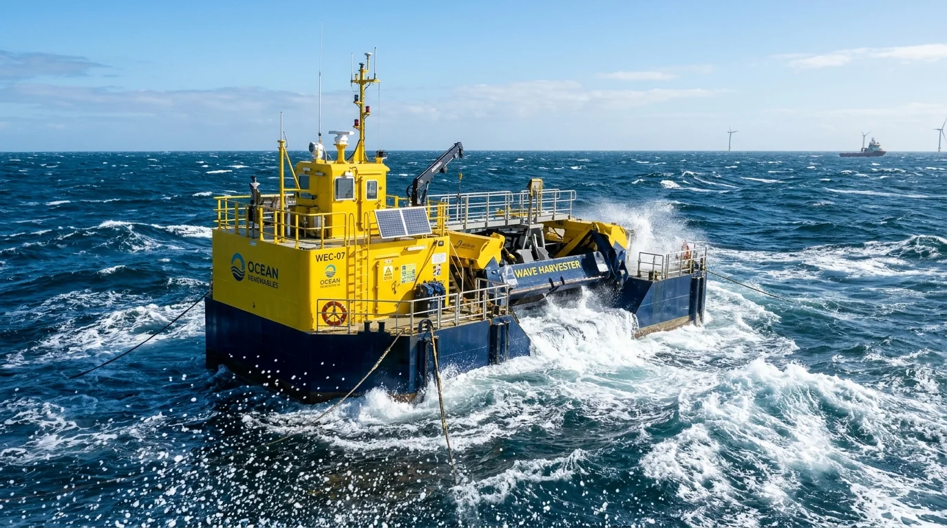
The world's oceans encompass over 70% of the planet's surface and act as an immense kinetic collector of solar and atmospheric energy. As winds sweep across open expanses of water, surface friction transfers momentum into ocean swells, concentrating diffused atmospheric energy into rhythmic hydrodynamic waves. According to global marine renewable resource syntheses published in the Intergovernmental Panel on Climate Change (IPCC) Special Report on Renewable Energy Sources (SRREN, Chapter 6: Ocean Energy, Section 6.2) and benchmark global wave hindcast models by Mørk et al. (OMAE 2010), the world's gross theoretical ocean wave energy resource is estimated at approximately 29,500 to 32,000 Terawatt-hours (TWh) per year (~30 to 32 PWh/year), with broader historical literature estimates spanning between 8,000 and 80,000 TWh/year depending on modeling boundaries and frequency cutoff thresholds. Crucially, however, the technically and economically harvestable electricity represents only a small fraction of this theoretical ceiling due to geographical distance, environmental exclusions, conversion losses, and grid integration constraints.
Despite this extraordinary theoretical potential, wave energy remains in a pre-commercial demonstration stage compared to mature renewable technologies like solar photovoltaics and onshore or offshore wind. Extracting reliable, cost-effective electrical power from an erratic, corrosive, and violently dynamic marine environment presents some of the most demanding engineering challenges in modern energy systems.
This technical guide explains how ocean wave energy conversion works from physics to grid interconnection, examines the five primary Wave Energy Converter (WEC) architectures, breaks down real-world conversion efficiency, reviews survivability challenges, analyzes the state of wave power development in India, and evaluates why utility-scale commercialization has faced historic delays.
1. What Is Wave Energy?
Wave energy is a concentrated secondary form of solar and wind energy. The process originates when differential solar heating of the Earth's atmosphere creates high- and low-pressure air masses. As air moves between these pressure zones, wind blows across the open ocean surface.
| Energy Conversion Stage | Physical Phenomenon | Typical Power Density Range |
|---|---|---|
| 1. Primary Solar Insolation | Electromagnetic radiation striking the atmosphere and ocean | 0.1 to 1.0 kW/m² (diffuse, day-dependent) |
| 2. Atmospheric Wind | Kinetic energy of moving air masses driven by thermal gradients | 0.5 to 2.5 kW/m² (turbulent, height-dependent) |
| 3. Ocean Wave Front | Hydraulic potential and kinetic energy concentrated at the water surface | 20 to 80+ kW per meter of wave crest width (dense, continuous) |
Note on physical metrics: Solar radiation and atmospheric wind are customarily quantified per unit cross-sectional area (kW/m²), whereas wave energy transport flux is expressed per unit length of wave crest front (kW/m). Because these metrics describe different geometric dimensions of resource flux, they provide a qualitative overview of energy concentration across conversion stages rather than a direct mathematical equivalence.
How Waves Store Energy: Kinetic vs. Potential
As wind blows across the water, tangential friction and normal pressure variations create small ripples (capillary waves). If the wind blows steadily over a large distance—known in oceanography as the fetch—and over an extended duration, these ripples grow into gravity waves.
Within an ocean wave, energy is stored in two distinct thermodynamic and physical forms:
- Potential Energy (Ep): Generated when water mass is lifted against gravity to form the wave crest above the mean water level.
- Kinetic Energy (Ek): Stored in the orbital, circular movement of water particles as the wave propagates forward. In deep water (depth greater than half the wavelength, d > λ/2), individual water particles do not travel continuously across the ocean; instead, they trace circular orbits in place, with orbital diameter decaying exponentially with depth.
Seawater is much denser than air (~1,025 kg/m³ for seawater versus ~1.225 kg/m³ for air at sea level), which contributes to substantial hydrodynamic forces on wave energy devices. However, the usable power available at a site depends on wave height, period, direction, water depth, and the converter's specific hydrodynamic design.
Wave Power Density Formula
In deep-water ocean engineering, the omnidirectional wave power transport per unit width of wave crest (expressed in kilowatts per meter, kW/m) for an irregular sea state is mathematically represented by the linear wave theory approximation:
Where:
- P: Wave energy flux (power per meter of wave crest, kW/m)
- ρ (Rho): Seawater mass density (nominally 1,025 kg/m³)
- g: Acceleration due to gravity (9.81 m/s²)
- Hm0 (or Hs): Significant wave height in meters (defined statistically as four times the standard deviation of surface elevation, roughly corresponding to the average height of the highest one-third of waves)
- Te: Energy period in seconds (the characteristic period of the wave spectrum, typically related to peak period Tp by Te ≈ 0.86 to 0.90 × Tp)
This formula demonstrates that wave power increases quadratically with wave height (H2) and linearly with wave period (T). For example, as an illustrative theoretical calculation (rather than an actual site measurement), an ideal deep-water sea state with a 3-meter significant wave height and a 10-second energy period yields roughly 0.49 × 32 × 10 ≈ 44.1 kW/m, illustrating why exposed open-ocean coastlines represent extraordinarily concentrated energy regimes.
2. How Wave Energy Conversion Works: Step-by-Step
Converting irregular, slow, high-force ocean waves into the steady, high-frequency, alternating current (AC) electricity demanded by modern power grids involves a sequential multi-stage energy conversion train. The engineering process flows progressively through six physical transitions: from incoming oceanic swells to hydrodynamic body capture, mechanical power take-off (PTO) transformation, rotational or linear electrical generation, active power electronics conditioning, and finally high-voltage subsea export transmission to the terrestrial utility grid.
The 6 Conversion Stages
- Wave Capture: An offshore or coastal structure (floating buoy, oscillating flap, partially submerged chamber, or ramp) interacts with incoming waves. The dynamic hydrodynamic forces exert heave (vertical), surge (horizontal), pitch (angular rocking), or water column oscillations on the device.
- Mechanical Transmission: The structural displacement creates relative mechanical motion. Because ocean waves typically cycle at low frequencies (0.05 to 0.2 Hz, or 1 cycle every 5 to 20 seconds), the raw captured mechanical motion is characterized by very high forces and slow velocities.
- Power Take-Off (PTO) Transformation: A mechanical system converts this slow, reciprocating, high-torque motion into a high-speed or steady mechanical drive. Important engineering note: A wave energy device does not necessarily require a hydraulic system. Depending on the architecture, PTO systems use high-pressure hydraulic pumps, bidirectional air turbines, mechanical gearboxes, or direct-drive linear electrical generators.
- Electrical Generation: An electrical generator (commonly a Permanent Magnet Synchronous Generator [PMSG] or Squirrel-Cage Induction Generator) converts the rotary or linear mechanical energy into raw electrical power.
- Power Conditioning & Smoothing: Because individual waves vary continuously in height and frequency, the generator produces erratic, variable-voltage, variable-frequency electricity. Power electronics (active rectifiers, DC-link capacitor banks or supercapacitor buffers, and grid-tied inverters) condition the signal into stable 50 Hz or 60 Hz AC voltage synchronized with grid codes.
- Subsea Transmission & Grid Delivery: Power flows through a flexible dynamic umbilical cable down to a seabed junction box, travels via an armored three-core subsea transmission cable to shore, passes through a coastal substation transformer, and enters the regional distribution or transmission grid.
3. Types of Wave Energy Converters (WECs)
Unlike wind energy, which converged on the horizontal-axis three-bladed turbine, or solar power, which standardized on planar photovoltaic modules, wave energy has produced dozens of distinct structural concepts. These designs arise from differing strategies to solve a fundamental hydrodynamic dilemma: how to capture non-linear, bidirectional wave motion while surviving destructive ocean storms.
The European Marine Energy Centre (EMEC) and the U.S. Department of Energy (DOE) categorize Wave Energy Converters into five primary operational archetypes:
A. Point Absorber
A Point Absorber is a floating or submerged buoyant structure whose horizontal dimensions are significantly smaller than the prevailing ocean wavelength (Characteristic Diameter ≪ λ).
Working Principle
Because of its compact footprint relative to prevailing wavelengths, a point absorber does not require mechanical yaw orientation to align with incoming wave crests. However, this omnidirectional characteristic does not imply that power capture is identical from every compass direction; actual power absorption is influenced by directional sea spectra, asymmetric hull or heave-plate geometry, and multi-line mooring stiffness. As waves pass, the buoyant float oscillates relative to a stationary or inertial reference—such as a rigid seabed anchor, a deeply submerged ballast plate, or a heavy floating spar that extends below wave action.
Components
- Floating Buoy / Floater: Lightweight, high-buoyancy steel or composite hull shaped to maximize hydrodynamic heave excitation.
- Reaction Structure / Heave Plate: A deep underwater plate providing added hydrodynamic mass and damping to serve as a stable inertial reference.
- Power Take-Off (PTO): Either high-pressure hydraulic cylinders driving a hydraulic motor, or a direct-drive linear permanent-magnet generator located inside the central spar.
- Mooring Spread: Taut synthetic tethers or catenary anchor chains that keep the device stationed while accommodating tidal variations.
Suitable Locations
Typical deployment locations vary by device design, mooring configuration and local bathymetry; some offshore concepts operate in deep water.
Advantages
- Does not require active yaw steering mechanisms to face changing wave directions.
- Compact structural size and modularity; multiple buoys can be deployed in utility-scale array clusters ("wave farms").
- Certain designs offer the operational option to submerge below peak surface storm waves during extreme sea states.
Limitations
- High cyclic snatch and snap loads on mooring lines during extreme seas.
- Complex seals required to protect linear bearings and hydraulic piston rods from marine fouling and saltwater intrusion.
B. Oscillating Water Column (OWC)
An Oscillating Water Column (OWC) is a hollow, partially submerged chamber open to the sea below the waterline, trapping a pocket of air above an enclosed water column.
Working Principle
As incoming ocean waves enter the chamber base, the water level inside rises and falls like a massive natural hydraulic piston. When the water column rises, it compresses the trapped air, forcing it through a narrow exhaust duct at the top. When the wave recedes, the water level drops, creating a partial vacuum that pulls air back down from the atmosphere.
To convert this alternating, bidirectional airflow into continuous unidirectional electrical rotation without complex mechanical valving, OWCs employ a specialized aerodynamic machine known as a Wells turbine (invented by Prof. Alan Wells in the 1970s). The Wells turbine employs symmetrical aerofoil blades arranged with their chord lines perpendicular to the duct airflow axis. When bidirectional air rushes alternately upward or downward through the rotor, the combination of axial airflow velocity and tangential blade motion creates a relative angle of attack that generates aerodynamic lift with a forward driving force, maintaining rotation in the exact same direction regardless of airflow reversal. Modern installations also evaluate self-rectifying biradial and impulse air turbines for improved operating bandwidth.
Components
- Air Chamber / Caisson: Heavy reinforced concrete or steel plenum chamber, frequently integrated into coastal breakwaters or deployed on floating offshore spars.
- Ducting & Throat: Specially contoured venturi nozzles designed to accelerate airflow into the turbine runner.
- Self-Rectifying Air Turbine: Wells turbine or bi-directional impulse turbine mounted directly above the chamber.
- High-Speed Generator: Conventional rotary generator coupled to the turbine shaft with a mechanical flywheel for short-term rotational inertia smoothing.
Suitable Locations
Shoreline cliffs, harbor breakwaters, nearshore rocky promontories (10–15 m depth), or large floating offshore buoys (such as the Mighty Whale concept or Ocean Energy OE Buoy).
Advantages
- Machinery housed above the waterline: The turbine, generator, and power conditioning systems operate in an elevated, dry atmospheric enclosure above sea level, greatly simplifying routine inspection and servicing. However, the submerged chamber structure and inner water column remain exposed to the marine environment.
- Excellent structural longevity when integrated into multi-purpose civil harbor breakwaters.
Limitations
- Low aerodynamic conversion efficiency at off-design flow rates (Wells turbines suffer from severe aerodynamic stall when airflow velocity exceeds rated design limits).
- High acoustic noise generated by the high-velocity oscillating air jet exiting the exhaust port.
- Large concrete caissons require substantial upfront civil construction capital.
C. Oscillating Wave Surge Converter (OWSC)
An Oscillating Wave Surge Converter (OWSC) is a bottom-hinged flap or paddle structure mounted perpendicular to the direction of wave travel in shallow to intermediate waters.
Working Principle
In deep open ocean water, wave particle motion is predominantly circular. However, as waves approach the coast and propagate into shallow to intermediate depths (typically 10 to 25 meters), shoaling, coastal wave transformation, and decreasing water depth compress these circular trajectories into pronounced horizontal, elliptical paths. The predominant hydrodynamic force transforms into a strong back-and-forth horizontal surge velocity.
An OWSC captures this surge motion using a buoyant vertical flap hinged to a seabed foundation. The forward and backward sweeping surge forces the flap to pitch back and forth like a pendulum. This slow, high-torque oscillatory movement actuates seabed-mounted hydraulic cylinders that pump pressurized fluid to shore or directly drive an enclosed onboard power module. Examples of this architecture include the Oyster device developed by Aquamarine Power and the WaveRoller system engineered by AW-Energy.
Components
- Oscillating Flap / Paddle: Buoyant rectangular steel or composite plate hinged along its lower edge.
- Seabed Base Frame: Heavy gravity foundation or pin-piled base secured directly to the bedrock seabed.
- Hydraulic Ram Assembly: Heavy-duty double-acting marine hydraulic cylinders connected between the flap and foundation.
- Subsea High-Pressure Pipe: Steel or composite hydraulic conduit carrying high-pressure water or biodegradable fluid to an onshore generator station or subsea pod.
Suitable Locations
Nearshore coastal zones with depths between 10 and 25 meters, ideally situated along rocky coastlines exposed to strong, consistent ocean swells.
Advantages
- Highly efficient extraction of shallow-water horizontal surge forces, which contain substantial energy per meter of coastline.
- In severe storms, certain flap designs incorporate survival modes to be flooded, unlatched, or ballasted to lie flat against the seabed, mitigating destructive breaking wave crest impacts.
- Reduced visual impact compared to tall offshore surface structures.
Limitations
- Foundation and hinge mechanisms must withstand enormous dynamic bending moments at the seabed pivot.
- Moving mechanical components are fully submerged in shallow, sediment-rich waters, accelerating abrasive wear from suspended sand and grit.
- Specialized shallow-draft heavy installation vessels and commercial divers are required for seabed anchoring.
D. Attenuator
An Attenuator is a long, multi-segment floating device oriented parallel to the principal direction of incoming wave propagation.
Working Principle
Rather than facing the wave broadside, an attenuator "rides" the wave along its length. Because the device is significantly longer than an individual wave crest, different segments of the machine rest simultaneously on different parts of the wave profile (e.g., the front section sits on a wave crest while the middle sits in a trough).
As the wave travels beneath the articulated cylindrical hulls, adjacent segments flex, pitch, and yaw relative to one another. Heavy-duty hydraulic cylinders bridged across the articulated universal joints are compressed and extended by this bending motion. The cylinders pump high-pressure hydraulic fluid through internal manifold circuits, driving hydraulic motors coupled to electric generators. The most celebrated historical example of this class was the Scottish Pelamis Wave Power machine.
Components
- Articulated Cylindrical Tubes: Series of buoyant tubular steel modules connected end-to-end by multi-axis flex joints.
- Articulated Joint Assemblies: Heavy forged steel universal hinges permitting both vertical (pitch) and horizontal (yaw) relative angular motion.
- Internal PTO Modules: Enclosed, hermetically sealed hydraulic power take-off pods containing rams, accumulators, hydraulic motors, and induction generators housed within the joint segments.
- Catenary Compliant Mooring: Slack-moored bow anchor system that naturally aligns the structure into the dominant wave heading via hydrodynamic drag ("weathervaning").
Suitable Locations
Deep-water offshore sites (50 to 100+ meters depth) located 5 to 20 kilometers from shore.
Advantages
- Slender, streamlined frontal profile minimizes broadside hydrodynamic shock loads during extreme storm conditions.
- Weathervaning capability allows passive self-alignment with changing swell directions.
- Modular joint design allows pre-commissioned PTO modules to be swapped out during dockside maintenance.
Limitations
- Extremely complex dynamic mechanical joints subjected to continuous multi-axial fatigue stress.
- High number of high-pressure hydraulic seals operating in an offshore marine environment increases the risk of component wear and fluid leakage.
- Long offshore towing distances required for shipyard refits.
E. Overtopping Device
An Overtopping Device is a floating or shoreline structure that utilizes a sloping ramp to capture the crests of incoming waves into an elevated reservoir above sea level.
Working Principle
When an ocean wave strikes the curved forward ramp of an overtopping device, its kinetic energy forces water to surge up the incline—a phenomenon known as wave run-up. The wave spills over the crest of the ramp into an internal, elevated water catchment basin situated higher than the surrounding ocean surface.
This process effectively converts the irregular dynamic kinetic energy of incoming waves into a stable, low-head hydrostatic potential energy reservoir. Water trapped inside the reservoir is released continuously back into the sea through submerged discharge conduits equipped with conventional low-head hydroelectric turbines (such as variable-pitch Kaplan or propeller turbines). The Wave Dragon floating platform and the shoreline SSG (Seawave Slot-Cone Generator) are prominent examples of this technology.
Components
- Curved Focusing Arms / Reflectors: Large floating wing barriers that concentrate and focus the incoming wave front toward the central ramp.
- Run-Up Ramp: Smoothly contoured inclined slope engineered to maximize wave run-up velocity.
- Elevated Reservoir: Water containment basin with an operating water head typically 1.5 to 4.0 meters above mean sea level.
- Low-Head Hydro Turbines: Multiple small Kaplan or bulb hydro turbines operating under low hydrostatic pressure heads.
Suitable Locations
Offshore floating deployments in deep water (Wave Dragon), or concrete civil installations integrated into coastal rocky headlands and harbor breakwaters (OBREC - Overtopping Breakwater for Energy Conversion).
Advantages
- Inherent Energy Storage: The elevated basin acts as a hydraulic buffer, converting erratic individual wave pulses into a more regulated turbine feed and substantially reducing the short-term electrical output fluctuations common to direct-acting oscillating converters.
- Employs proven, mature, off-the-shelf low-head hydroelectric turbine technologies with known operating histories.
Limitations
- Enormous physical size, displacement, and mass required to retain sufficient water volume (a floating commercial Wave Dragon displaces over 20,000 to 30,000 metric tons).
- Substantial capital expenditure for civil engineering and structural materials.
- Low hydraulic head (1.5 to 3.5 m) yields low thermodynamic water-to-shaft conversion efficiency per cubic meter of water captured.
Table A: Comprehensive Comparison of Wave Energy Converter (WEC) Architectures
| Converter Architecture | Hydrodynamic Capture Principle | Standard PTO Mechanism | Typical Deployment Zone | Key Engineering Advantages | Primary Technical Limitations |
|---|---|---|---|---|---|
| Point Absorber | Vertical heave / multi-mode oscillation of compact buoy relative to reference | Hydraulic cylinders + motor, or direct-drive linear generator | Offshore (40–100+ m depth) | No active yaw needed; modular array scalability; compact geometry | Cyclic mooring snap loads; sliding seals vulnerable to marine biofouling |
| Oscillating Water Column (OWC) | Reciprocating seawater column compressing/expanding air volume | Self-rectifying air turbine (Wells, biradial, impulse) | Shoreline breakwaters, nearshore, or floating spars | Turbine and electrical systems housed above waterline in dry chamber | Aerodynamic turbine stall; loud acoustic exhaust; expensive civil caissons |
| Oscillating Wave Surge Converter (OWSC) | Pitching oscillation of bottom-hinged flap driven by horizontal wave surge | High-pressure hydraulic cylinders driving motor or onshore generator | Nearshore (10–25 m depth) | Captures powerful shallow-water surge; flap can lie flat in severe seas | High seabed pivot bending moments; abrasive sand/sediment wear on joints |
| Attenuator | Relative multi-axis bending between articulated floating cylindrical segments | Hydraulic rams at joints driving hydraulic motors | Offshore (50–100 m depth) | Slender profile minimizes extreme broadside storm loads; weathervaning | High structural fatigue on universal joints; numerous hydraulic seals |
| Overtopping Device | Wave run-up over an inclined ramp into an elevated catchment basin | Low-head hydroelectric Kaplan or propeller turbines | Offshore floating or integrated breakwater | Inherent hydraulic storage buffers output; uses mature hydro turbines | Colossal physical displacement and structural mass; low operating head |
4. Key Subsystems of a Complete Wave Energy Plant
Regardless of the specific hydrodynamic archetype selected, a complete, utility-interconnected Wave Energy Converter consists of six core physical subsystems:
- The Hydrodynamic Body (Hull / Floater): Fabricated from marine-grade carbon steel with specialized protective coatings, reinforced pre-stressed concrete, or advanced vacuum-infused fiberglass/carbon composites. It must provide sufficient structural buoyancy, fatigue resistance against millions of loading cycles over time depending on local wave climates and operating conditions, and hydrodynamic shaping tailored to prevailing ocean wave spectra.
- The Reaction System (Inertial Base or Mooring): To extract energy from wave motion, a force must react against an opposing resistance. This is provided by fixed seabed structures (drilled rock monopiles, suction caissons, gravity concrete blocks) or compliant floating reaction plates that utilize deep, quiescent water layers as inertial anchors.
- The Power Take-Off (PTO) Unit: The functional "heart" of the WEC. It converts fluctuating mechanical displacement into steady rotary or direct electrical motion. Technologies include:
- Hydraulic Systems: Piston pumps, fluid accumulators for pressure smoothing, high-displacement swashplate motors, and relief valves.
- Direct-Drive Electrical Generators: Permanent-magnet linear or rotary machines eliminating intermediate mechanical fluids.
- Air Turbines: Wells or impulse aerodynamic machines operating on bidirectional air flows.
- Mooring and Station-Keeping Spread: Essential for floating offshore devices. Common configurations include taut synthetic nylon/polyester lines with inline elastomeric load dampers, compliant catenary steel chain spreads, or tension-leg vertical tethers. The mooring spread must be designed for site-specific extreme environmental conditions, including severe storm loads, while allowing the device's intended oscillatory motion.
- Power Conditioning & Subsea Electrical Architecture: Housed within a hermetically sealed, nitrogen-purged internal pod. Includes four-quadrant IGBT power converters, step-up transformers (typically elevating generated voltage from 690 V to 11 kV or 33 kV), switchgear, and protective relays.
- Dynamic Subsea Umbilical & Export Cable: A flexible, reinforced, double-armored marine electrical cable that connects the moving offshore WEC to the stationary seabed transmission line. The dynamic umbilical is supported in the water column using a "lazy-S" or "steep-wave" buoyancy module configuration to prevent bending fatigue and mechanical chafing.
5. Wave Energy Efficiency and Performance Physics
Evaluating the efficiency of a wave energy converter is significantly more complex than rating a traditional thermal power plant or solar module. In wave energy engineering, broad claims of an overall percentage efficiency can be misleading because energy extraction involves cascaded hydrodynamic, mechanical, and electrical stages whose performance fluctuates continuously with changing sea states.
The Energy Conversion Chain: Measured vs. Modeled Performance
In technical evaluations, engineers distinguish between measured offshore prototype performance, scale-model laboratory flume tests, and numerical hydrodynamic simulations. Progressive energy transformation occurs across three distinct physical and electromechanical stages:
- Hydrodynamic Capture Stage:
The primary extraction phase where ocean swells interact with the physical hull, buoy, or flap. Energy losses occur through wave scattering, radiation damping, viscous boundary-layer friction against the hull, and hydrodynamic phase misalignment when ocean wave periods drift away from the device's resonant tuning. - Power Take-Off (PTO) Mechanical Conversion:
The intermediate mechanical transformation converting slow oscillatory motion into high-speed rotary or linear thrust. Losses stem from hydraulic seal friction, fluid throttling through directional and pressure-relief valves, volumetric pump leakage, or aerodynamic boundary stall within air turbine runners. - Electromechanical and Power Conditioning Stage:
The final stage converting shaft torque or magnetic flux into utility-grade AC electricity. Losses occur as copper resistive losses (I2R heating) in generator windings, magnetic core hysteresis, transformer core losses, and solid-state IGBT switching dissipation in active rectifiers and grid-tied inverters.
Because each stage is subject to sea-state variability, control algorithm responsiveness, and site-specific wave spectral shapes, net "wave-to-wire" efficiency cannot be summarized by a single industry-wide constant. In marine energy engineering and electromechanical scaling evaluations, converter efficiency and optimal operating points vary substantially depending on local wave climates, electrical generator sizing, and reactive control strategies.
Capture Width and Capture Width Ratio (CWR)
Marine engineers evaluate hydrodynamic performance using the concept of Capture Width (Cw), defined as the ratio of captured mechanical power to the incident wave power density:
To compare devices of different physical sizes, engineers calculate the non-dimensional Capture Width Ratio (CWR):
Where B is the characteristic physical dimension of the device (such as buoy diameter or flap width). According to linear wave theory principles established by Budal, Evans, and Falnes, an idealized axisymmetric point absorber oscillating purely in heave under optimal resonance conditions has a theoretical maximum absorption width limit of Cw = λ ÷ 2π (where λ is wavelength). In practice, however, real-world CWR values are substantially lower and vary depending on hull geometry, multidirectional sea states, active phase-control implementation, and the specific definition of dimension B applied.
Understanding Capacity Factor vs. Device Efficiency
A critical distinction exists between instantaneous device efficiency and operational capacity factor:
- Device Efficiency (Wave-to-Wire): The instantaneous ratio of electrical power delivered to the grid divided by the total wave energy crossing the device's capture aperture for a given sea state.
- Capacity Factor (CF): The ratio of actual electrical energy generated over a full calendar year divided by the theoretical output if the plant operated at its maximum nameplate rated capacity continuously for all 8,760 hours of the year:
In wave energy engineering, determining a standardized nameplate capacity (Prated) is inherently challenging. Because wave energy flux varies dramatically between calm summer months and severe winter storms, oversizing the generator and PTO for rare storm peaks leads to low utilization during typical moderate seas, whereas undersizing risks wasting peak wave energy. Consequently, capacity factors depend heavily on developer sizing choices, site-specific seasonal distributions, and control dynamics rather than following a fixed universal benchmark.
Average Power Calculation
The actual average power output (Paverage) delivered by a wave energy system over an operational duration t is calculated by dividing total electrical energy exported by time:
Where:
- Paverage: Mean active electrical power delivered to the grid (kW or MW)
- Egenerated: Total electrical energy exported over period t (kWh or MWh)
- t: Total operational duration in hours
Maximizing Paverage requires active control engineering—such as latching control (mechanically locking the oscillating body at maximum stroke and releasing it in phase with the passing wave) or reactive phase tuning—to continuously match the device's natural oscillation frequency to the shifting peak frequency of incoming ocean swells.
6. Site Selection and Oceanographic Requirements
Deploying wave energy devices requires rigorous marine geophysical, metocean, and oceanographic resource analysis. Suitable sites must satisfy four primary physical criteria:
- Incident Wave Climate (Hs and Te):
- Certain project-specific feasibility studies adopt an average annual wave power density of around 20 to 30 kW/m as an exploratory reference benchmark; however, this is not a universal minimum requirement, and economically viable thresholds depend strongly on converter architecture, local power purchase rates, and grid connection economics.
- Ideal sea states feature consistent, long-period oceanic swells (Te ≈ 8 to 14 seconds) rather than short-period, choppy, wind-generated seas (Te < 5 seconds), which dissipate rapidly and deliver poor PTO excitation.
- Water Depth Classification:
- Deep Water (> 40–50 m): Frequently favored by deep-water floating concepts and offshore attenuators to capture open swells without seabed frictional energy dissipation.
- Intermediate/Shallow Water (10–25 m): Optimal for bottom-hinged oscillating wave surge converters (OWSCs) that rely on compressed horizontal elliptical wave surge.
- Shoreline / Intertidal: Suitable for concrete breakwater-integrated OWCs and shoreline overtopping systems, eliminating subsea cabling but capturing lower wave energy due to shallow-water shoaling dissipation.
- Seabed Bathymetry and Geotechnical Conditions:
- Anchorage requires stable geological substrates. Rocky bedrock allows drilled pin-piling and rock anchor grouting; firm sand and clay permit high-holding-power drag-embedment anchors or suction caissons. Shifting sandbanks, deep unconsolidated silt, or seismically active fault zones complicate foundation stability.
- Grid Interconnection and Port Logistics:
- Proximity to a high-voltage coastal electrical substation (preferably within 5 to 20 km) is essential to minimize expensive high-voltage alternating current (HVAC) subsea cable costs.
- The site must be located within practical towing distance (under 50 to 100 nautical miles) of a deep-water commercial port with crane-equipped quaysides capable of handling heavy assembly, dry-docking, and maintenance operations.
- Marine Spatial Planning (MSP):
- Deployment zones must be deconflicted from international commercial shipping channels, naval exercise sectors, commercial bottom-trawling fisheries, offshore telecom fiber-optic corridors, and sensitive marine protected areas (MPAs).
7. Engineering Challenges: Why Wave Power Has Lagged Behind
While wind and solar power have achieved rapid commercial scale, wave energy has progressed far more slowly. The reasons are fundamentally rooted in the harsh nature of the ocean environment. Comprehensive marine engineering studies from ocean energy test centers and academic research groups identify survivability, mooring fatigue, and offshore intervention logistics as the primary impediments to commercial viability.
| Engineering Challenge | Physical / Mechanical Impact | Proven Engineering Mitigation Strategies |
|---|---|---|
| Marine Corrosion | Aggressive galvanic and electrochemical corrosion of structural steel, hydraulic rods, and electrical enclosures | Sacrificial zinc/aluminum anodes; thermal-spray aluminum (TSA) coatings; thick marine epoxies; duplex stainless steels (e.g., 25Cr) |
| Biofouling | Accumulation of barnacles, mussels, and kelp adds parasitic deadweight, changes buoyancy, and increases hydrodynamic drag | Non-toxic silicone foul-release polymer coatings; copper-nickel cladding; automated underwater ultrasonic anti-fouling transducers |
| Mooring & Mechanical Fatigue | Continuous cyclic loading over millions of wave cycles induces micro-cracks, metal fatigue, and potential tether or chain failures | Elastomeric inline load-attenuation tethers; high-strength synthetic polyester/HMPE lines; finite-element fatigue safety margins |
| Extreme Storm Survivability | Extreme storm swells deliver destructive hydrodynamic forces substantially higher than nominal operational design loads | Device-specific survival strategies: controllable ballasting to submerge buoys below surface waves, hydrodynamic detuning, pressure-relief PTO bypass, or resting flaps flat against the seabed |
| Subsea Cable Failure | Dynamic flexing, vortex-induced vibration (VIV), and seabed rock abrasion rupture insulation and optical telemetry fibers | Double-armored dynamic subsea cables; polyurethane bend restrictors; rock trenching; concrete split-pipe mattressing |
| Offshore Logistics & Downtime | High charter costs for dynamic positioning (DP) vessels and tugs; narrow weather windows delay maintenance interventions | Modular dockside-swappable PTO pods; remote health monitoring sensors; robust component redundancy; simplified offshore latching |
The Survivability Paradox
In ocean energy engineering, hydrodynamic forces during severe storm sea states can be vastly higher than nominal operational design loads. Designing a structural chassis capable of surviving extreme sea states without making it prohibitively heavy and capital-intensive for normal operational power generation is known as the Wave Energy Survivability Paradox. Metocean design criteria and extreme storm thresholds vary significantly by location and regional wave climate. Several early demonstration prototypes, such as the Osprey OWC off Scotland and early full-scale prototypes off the coasts of Portugal and Australia, suffered terminal structural or mooring failures when subjected to unpredicted extreme storm swells.
8. Environmental and Marine Ecosystem Impacts
Wave energy converters produce zero direct greenhouse gas emissions during operation. However, placing industrial mechanical structures into coastal and offshore marine environments creates ecological interactions that require ongoing environmental monitoring and risk management, as documented by research initiatives such as the Pacific Northwest National Laboratory (PNNL) Tethys database and the Triton Initiative:
- Artificial Reef and FAD Effect: Subsea foundations, mooring chains, and submerged hulls provide hard substrate colonized by algae, anemones, and mussels, effectively acting as artificial reefs. Floating platforms frequently function as Fish Aggregation Devices (FADs), creating localized habitats that attract pelagic fish, seabirds, and marine mammals.
- Underwater Acoustic Emissions: Operational noise is generated by high-speed hydraulic swashplate pumps, air turbine venting, and mechanical bearings. Marine biologists study these acoustic signatures to ensure sound pressure levels (SPL) remain well below regulatory thresholds that could disrupt marine mammal echolocation (e.g., dolphins, porpoises, and baleen whales).
- Seabed Footprint and Benthic Disturbance: Direct physical disturbance is limited to the anchor footprint (drag embedment, drilled monopiles, or concrete gravity bases). Catenary anchor chains, however, can sweep across the sea floor as the device shifts, potentially damaging sensitive benthic seagrass beds or coral reef communities if not designed with buoyant mid-line support floats.
- Nearshore Hydrodynamic and Sediment Alterations: Large arrays of wave energy converters extract significant energy from incoming wave trains. In nearshore environments, this energy depletion can alter wave breaking dynamics, potentially modifying longshore currents and localized sand deposition patterns along sandy coastlines.
- Navigation Hazard and Collision Mitigation: Floating devices present collision hazards for commercial cargo, fishing vessels, and recreational craft. WECs are equipped with self-powered radar reflectors, AIS (Automatic Identification System) marine transponders, high-visibility marine yellow paint schemes, and standardized IALA navigational flashing beacons.
9. Wave Energy Economics: Capital, Operating Costs, and LCOE
Technology maturity in the wave energy sector varies significantly across device archetypes and developers—ranging from numerical modeling and laboratory flume tests (TRL 3–4) to full-scale single-device open-ocean trials (TRL 6–7) and small pilot arrays (TRL 7–8). Consequently, economic metrics reflect high first-of-a-kind (FOAK) engineering, bespoke fabrication, and specialized marine operational expenses:
Cost Structure Breakdown
- Capital Expenditures (CAPEX):
- Device Fabrication (35–45%): Heavy marine-grade steel or concrete construction, precision machining of PTO components, and specialized protective marine coating systems.
- Mooring, Anchors & Subsea Foundation (15–20%): Specialized anchor handling tug supply (AHTS) vessels and offshore installation equipment.
- Electrical Infrastructure & Cabling (15–20%): Subsea dynamic power cables, offshore junction nodes, directional drilling for shoreline landfall, and substation connection.
- Installation & Marine Operations (15–25%): Specialized vessel charters, commercial diving operations, and remote operated vehicle (ROV) teams.
- Operational Expenditures (OPEX):
- Marine operational expenditures represent a major share of lifetime costs. Offshore inspection, maintenance, and repair require specialized offshore support vessels, calm weather windows, and specialized maritime crews, which can quickly inflate operational budgets if unpredicted component failures occur.
- Levelized Cost of Energy (LCOE):
- Because the global wave energy sector comprises diverse prototype concepts without high-volume mass production, published Levelized Cost of Energy (LCOE) figures represent model-specific and project-specific estimates rather than standardized market benchmarks. LCOE values vary considerably depending on local metocean resource strength, capital discount rates, export cable distances, and operational availability. At present, wave energy remains significantly more capital-intensive than mature utility-scale solar PV and onshore wind.
The Path to Commercial Parity
Wave energy does not need to compete directly with base-load terrestrial solar in desert regions. Instead, its primary value proposition lies in:
- Seasonal and Daily Grid Balancing: Waves often peak during winter months and persist through the night when solar output drops to zero, providing counter-cyclical grid stabilization.
- Remote Islands and Off-Grid Coastal Communities: In isolated island grids (such as parts of Hawaii, Caribbean islands, Pacific nations, Lakshadweep, and the Andaman & Nicobar archipelago), electricity is frequently generated using imported diesel fuel with high logistical transport overhead. In these microgrid environments, marine renewable power has an earlier opportunity to achieve economic parity than in bulk mainland utility markets.
- Serial Manufacturing and Array Scale: Moving from bespoke, one-off prototype fabrication to standardized assembly lines and multi-device commercial arrays will drive substantial cost reductions via economies of scale, similar to cost trajectories observed in offshore wind over the past two decades.
10. Wave Energy in India: Coastal Potential and Development Status
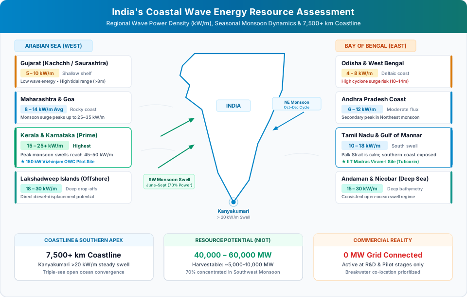
With an extensive peninsular coastline of over 7,500 kilometers bordering the Arabian Sea and the Bay of Bengal, India possesses substantial ocean energy resources. However, developing commercial wave power along the Indian coast involves distinct geographic, meteorological, and economic realities.
India's Wave Climate and Resource Assessment
Official government evaluations and parliamentary records reflect India's significant marine energy potential. In parliamentary replies by the Ministry of New and Renewable Energy (MNRE), notably in Lok Sabha Unstarred Question No. 1514 (tabled on 4 December 2024; citing a comprehensive baseline roadmap study conducted by IIT Madras and CRISIL in 2014), the government reported India's estimated theoretical wave power potential at approximately 41,300 MW (around 41.3 GW) along its peninsular coastline. However, the government emphasized that wave energy remains in a nascent research and development stage in the country, and that economically exploitable potential requires extensive site-specific metocean measurement.
The Indian wave climate exhibits distinct regional and seasonal characteristics:
- Southwest Monsoon Seasonality: A substantial share of India's annual wave energy occurs during the four months of the Southwest Monsoon (June to September), driven by strong seasonal winds across the Arabian Sea. During the post-monsoon and calm winter months, wave power flux drops to modest levels.
- The Western Coast Advantage: States along the Arabian Sea—particularly Kerala, Karnataka, Maharashtra, and Goa—consistently exhibit higher mean annual wave power densities than the eastern coast bordering the Bay of Bengal.
- The Southern Tip (Kanyakumari): The southern tip of the Indian peninsula receives unhindered, long-period oceanic swells originating in the Southern Ocean, maintaining consistent wave activity throughout the year.
- Island Territories: The Andaman & Nicobar Islands and Lakshadweep Archipelago feature deep water close to shore and heavy exposure to oceanic swells, making them prime candidates for wave energy deployment to displace expensive, polluting diesel generators.
Research, Pilot Demonstrations, and Breakwater Integration
India was one of the early pioneers in shoreline wave energy research:
- The Vizhinjam OWC Pilot (Kerala): In 1991, researchers from the Indian Institute of Technology (IIT) Madras, in collaboration with the Department of Ocean Development (now the Ministry of Earth Sciences), designed and commissioned India's pioneering 150 kW Oscillating Water Column pilot plant integrated into the harbor breakwater at Vizhinjam, near Thiruvananthapuram. The experimental facility used a concrete caisson and a vertical-shaft Wells air turbine, providing landmark real-sea operational data on breakwater air-turbine aerodynamics over extended trial periods, as documented in peer-reviewed literature by Ravindran and Koola (1991, Current Science).
- IIT Madras Research - Sindhuja-1: Marine engineering research has advanced toward floating offshore converters through the Sindhuja-1 project, developed by IIT Madras (Department of Ocean Engineering, led by Prof. Abdus Samad) in partnership with industry. In November 2022, researchers completed open-sea deployment trials of the point-absorber prototype located approximately 6 kilometers off the coast of Tuticorin (Thoothukudi, Tamil Nadu) in water depths of roughly 20 meters. Designed with a central spar and floating buoy driving an electrical power take-off module, the initial ~100 W research prototype successfully validated wave-induced vertical oscillation dynamics and offshore station-keeping, with technical findings presented in the Proceedings of the 15th European Wave and Tidal Energy Conference (EWTEC 2023) and NIOT symposia.
- Multi-Purpose Coastal Infrastructure: To resolve the high capital costs of wave energy, Indian researchers actively investigate integrating wave energy converters directly into proposed coastal defense infrastructure, such as port breakwaters, coastal erosion seawalls, and offshore fishing harbors.
Current Commercial Reality in India
It is vital to maintain factual accuracy: There are currently no commercial utility-scale wave energy power plants operating on India's national electricity grid.
All wave energy activity in India remains at the research, academic pilot, and government demonstration scale under institutions such as NIOT and IITs, supported by the Ministry of New and Renewable Energy (MNRE). Key obstacles preventing commercialization include high capital costs, extreme seasonal resource variability, competing maritime space use with coastal fishing communities, and the availability of highly cost-effective terrestrial solar power throughout most of the country.
11. Comparison: Wave Energy vs. Tidal Energy vs. OTEC
Wave energy is frequently confused with other marine energy technologies. However, the three primary ocean energy systems utilize entirely different physical phenomena, equipment, and geographical conditions:
| Comparative Parameter | Wave Energy | Tidal Energy (Stream & Barrage) | Ocean Thermal Energy (OTEC) |
|---|---|---|---|
| Primary Energy Source | Wind blowing across ocean surface (concentrated solar/kinetic energy) | Gravitational pull of the Moon and Sun combined with Earth's rotation | Solar thermal heating of surface seawater vs deep ocean polar currents |
| Operating Principle | Mechanical oscillation (heave, pitch, surge, water column rise) | Hydrokinetic horizontal water flow through submerged tidal turbines (or head in barrage) | Thermodynamic Rankine heat engine operating across a ~20°C temperature gradient |
| Key Equipment | Buoys, flaps, Wells air turbines, hydraulic PTOs, compliant mooring | Subsea horizontal-axis hydro turbines, gravity bases, or tidal barrages | Evaporators, condensers, vacuum pumps, deep-sea cold water intake pipes (1,000 m) |
| Resource Predictability | Predictable 24–72 hours in advance using meteorological swell forecasting; accuracy varies by location and weather patterns | Highly predictable astronomical cycles (lunar and solar orbital periodicities) | Designed for continuous operation, subject to system availability; small diurnal temperature changes |
| Optimal Site Criteria | Open-ocean coastlines with high wind fetch, long periods, and exposed swells | Narrow straits, tidal estuaries, sounds, and headlands with flow speeds > 2.0 m/s | Equatorial/tropical waters with surface temperature > 25°C and depth > 800–1,000 m |
| Primary Engineering Barrier | Extreme storm survivability paradox, extreme cyclic fatigue, and mooring loads | High cavitation, marine growth on turbine blades, and limited global sites | Parasitic pumping load (deep cold-water pipe) and low Carnot thermodynamic efficiency (system-specific, typically under 3–5%) |
| Current Commercial Status | Pre-commercial prototyping, small pilot arrays, and demonstration testing | Commercial tidal barrages operational (e.g., Sihwa Lake, La Rance); tidal stream scaling | Kilowatt-scale pilot plants (Hawaii, Japan); 1–10 MW designs in development |
12. Advantages and Limitations of Wave Energy
A balanced evaluation of wave energy highlights both its engineering appeal and significant real-world constraints:
Advantages
- High Energy Density: Seawater provides high volumetric hydrodynamic forces compared to atmospheric airflow, allowing compact frontal capture profiles.
- Forecasting Potential: Ocean swells travel across thousands of kilometers of open ocean with measurable dispersion. Satellite radar and oceanographic buoys enable wave forecasting 24 to 72 hours in advance to aid grid dispatch planning, though local accuracy depends on coastal complexity and weather conditions.
- Low Visual and Land Footprint: Offshore wave devices sit low in the water, avoiding the visual landscape footprint of tall onshore wind turbines or the extensive land requirements of ground-mounted solar farms.
- Complementary Seasonal Profile: In many temperate and sub-tropical regions, wave energy peaks during winter months, directly matching seasonal peak heating and lighting electricity demands when solar resources are lowest.
- Co-Location and Hybrid Synergies: Can be co-located with floating offshore wind farms to share expensive subsea export cables, offshore substations, and maintenance vessel fleets.
Limitations
- Hostile Operating Environment: Relentless exposure to saltwater corrosion, marine biofouling, and abrasive suspended sediments degrades materials and seals.
- Severe Mechanical Fatigue: Structures experience tens of millions of continuous, irregular load cycles throughout a 20- to 25-year design life, elevating the risk of structural joint failure.
- High Early-Stage CAPEX and Logistics: Current prototype fabrication and specialized marine logistics make wave power significantly more capital-intensive than mature solar and onshore wind technologies.
- Lack of Design Standardization: The ocean energy industry has not yet converged on a single standardized technology architecture, diluting supply chain development and investor confidence.
- Storm Load Management: Designing structures capable of surviving severe storm conditions without incurring excessive capital expenditure remains an ongoing engineering challenge.
13. The Future of Wave Energy: Next-Generation Innovation
Despite past setbacks, the wave energy sector is advancing through systematic, standards-driven engineering. Several international developments are shaping the next decade of wave power:
- Dedicated National Test Facilities: Facilities such as the European Marine Energy Centre (EMEC) in Orkney, Scotland, the Biscay Marine Energy Platform (BiMEP) in Spain, and the PacWave grid-connected open-ocean test facility off the coast of Oregon, USA (pacwaveenergy.org), provide pre-permitted berths and subsea cable infrastructure, allowing developers to validate commercial-scale devices in real seas at reduced cost.
- Research in Adaptive and Predictive Control: Researchers are evaluating machine learning algorithms and predictive LiDAR wave measurement to proactively adjust PTO damping seconds before irregular wave crests arrive, optimizing energy capture during moderate seas while detuning during severe peak waves.
- Exploration of Advanced Composite Materials: Research into corrosion-proof elastomeric polymers, reinforced thermoplastics, and fiberglass composites seeks to reduce deadweight, lower fabrication costs, and mitigate saltwater corrosion.
- Niche Blue Economy and Microgrid Applications: Rather than attempting to immediately replace bulk terrestrial grid generation, wave energy developers are exploring dedicated offshore and remote applications:
- Powering autonomous offshore aquaculture fish farms.
- Supplying continuous subsea electrical power to underwater scientific and environmental sensor networks.
- Driving containerized offshore reverse osmosis seawater desalination systems to produce fresh drinking water directly at sea.
14. Frequently Asked Questions (FAQs)
1. Why is wave energy not widely used compared to solar and wind?
Wave energy has developed more slowly due to the harsh marine operating environment. Seawater causes severe corrosion, biological fouling (barnacles and algae), and intense mechanical fatigue over millions of continuous wave cycles. Crucially, converters must withstand extreme storm swells that exert forces many times higher than nominal operational design loads. These challenges have resulted in high capital expenditures, specialized offshore logistics, and slower commercialization compared to mature terrestrial renewables.
2. How much electricity can a single wave energy converter generate?
Individual prototype ratings vary widely, and examples range from small experimental sub-kilowatt or multi-kilowatt devices to larger demonstration systems rated up to several hundred kilowatts or megawatts. Because wave climates vary with seasons and locations, a device's actual electrical output depends on local wave heights, wave periods, and conversion efficiency. Sizing generators and establishing standard nameplate ratings remains an ongoing industry effort, making annual energy generation highly site-specific.
3. Do all wave energy devices use hydraulic systems?
No. While many point absorbers, attenuators, and oscillating wave surge converters use hydraulic cylinders and fluid motors as their Power Take-Off (PTO) system, other architectures use completely different mechanisms. Oscillating Water Columns (OWCs) use bidirectional aerodynamic Wells or impulse air turbines, overtopping devices use low-head hydroelectric Kaplan turbines, and certain point absorbers employ direct-drive linear permanent-magnet electrical generators without any hydraulic fluid.
4. How do wave energy devices survive massive ocean storms?
Modern wave energy converters incorporate device-specific "survival modes." Depending on the architecture, devices may detune their oscillation frequency, open hydraulic bypass relief valves, or lock mechanical joints. In some point absorber designs, controllable ballast tanks allow the buoy to submerge beneath violent surface waves, while certain bottom-hinged flaps can be decoupled to rest flat against the seabed until severe storm conditions subside.
5. What is the difference between wave energy and tidal energy?
Wave energy is generated by surface winds blowing across the open ocean, which creates kinetic and potential energy in surface waves. In contrast, tidal energy is driven by the gravitational pull of the Moon and Sun combined with the Earth's rotation, producing predictable, periodic bulk movements of coastal water masses. While wave energy fluctuates with seasonal weather patterns, tidal cycles are highly predictable decades in advance through astronomical cycles regardless of the weather.
6. Are wave energy converters dangerous to marine life?
Research syntheses from initiatives such as the Pacific Northwest National Laboratory (PNNL) Tethys database and the Triton Initiative indicate that potential environmental interactions require site-specific baseline studies and ongoing monitoring. Key areas of investigation include underwater acoustic emissions from PTO machinery, mooring line entanglements, localized benthic footprint and chain sweep, electromagnetic fields from dynamic subsea cables, and potential alterations to nearshore sediment transport.
7. Does India have operational commercial wave power plants?
No commercial utility-scale wave energy plants currently supply electricity to India's national grid. According to official parliamentary records from the Ministry of New and Renewable Energy (notably Lok Sabha Unstarred Question No. 1514, citing an IIT Madras–CRISIL baseline roadmap), India's estimated theoretical wave power potential is approximately 41,300 MW, while emphasizing that wave technology remains in a nascent R&D stage. India has conducted pioneering marine engineering research, including the historical 150 kW Vizhinjam breakwater OWC pilot in Kerala (documented by Ravindran and Koola in Current Science) and the Sindhuja-1 point absorber research prototype (~100 W) sea-tested by IIT Madras off Tuticorin.
8. How are maintenance and operational lifespans managed for wave energy converters?
Operational lifespans and maintenance intervals vary widely depending on device architecture, structural materials (such as carbon steel vs. advanced composites), and the metocean severity of the deployment site. Managing subsea electrical cables, hydraulic seals, mooring lines, and corrosion-protection systems requires planned maritime inspection cycles and modular, dockside-swappable components to minimize costly offshore vessel interventions.
References and Authoritative Resources
- European Marine Energy Centre (EMEC): Wave Device Architectures, Marine Test Berths, and Classification Standards. emec.org.uk/marine-energy/wave-devices
- U.S. Department of Energy (DOE) - Water Power Technologies Office: Marine Energy Glossary and Converter System Taxonomy. energy.gov/cmei/water/marine-energy-glossary
- Pacific Northwest National Laboratory (PNNL) - Tethys: OES-Environmental 2024 State of the Science Report: Environmental Effects of Marine Renewable Energy Development Around the World. tethys.pnnl.gov/publications/state-of-the-science-2024
- Intergovernmental Panel on Climate Change (IPCC): Special Report on Renewable Energy Sources and Climate Change Mitigation (SRREN), Chapter 6: Ocean Energy (Section 6.2: Wave Resource Assessment, pp. 503–505). ipcc.ch/report/renewable-energy-sources-and-climate-change-mitigation | IEA-OES Annual Report Synthesis: tethys.pnnl.gov/sites/default/files/publications/oes-annual-report-2025.pdf
- National Institute of Ocean Technology (NIOT): Ministry of Earth Sciences, Government of India: Ocean Energy and Marine Renewable Technologies Division. niot.res.in
- IIT Madras - Department of Ocean Engineering: Open Sea Trial of a Wave-Energy Converter at Tuticorin Port – Challenges (Sindhuja-1). By Abdus Samad et al., Proceedings of the 15th European Wave and Tidal Energy Conference (EWTEC 2023). researchgate.net/publication/374246830
- Current Science (Indian Academy of Sciences): Energy from sea waves—The Indian wave energy programme (Vizhinjam 150 kW Breakwater OWC Plant). By M. Ravindran & P. M. Koola (Vol. 60, No. 12, pp. 676–680, 1991). jstor.org/stable/24093688 | tethys-engineering.pnnl.gov/publications/energy-sea-waves-indian-wave-energy-programme
- Parliament of India (Lok Sabha): Ministry of New and Renewable Energy, Unstarred Question No. 1514 (Answered on 04 December 2024, citing IIT Madras–CRISIL 2014 study: 41,300 MW Wave Energy Potential). sansad.in/ls/questions/questions-and-answers
- PacWave (Oregon State University): PacWave Grid-Connected Open-Ocean Wave Energy Testing Facility Overview and Permitted Berths. pacwaveenergy.org