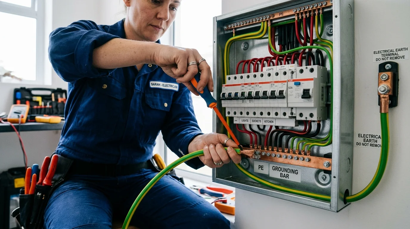
Electrical earthing (grounding) is the silent safety foundation of every modern residential electrical installation. A correctly installed protective-earthing system provides a fault-current path that helps the appropriate protective device disconnect the supply. The effectiveness of this protection depends on the earthing arrangement, conductor continuity, fault-loop impedance, and correct operation of the protective device.
While homeowners regularly track their home electricity meter readings or calculate appliance running expenses using an appliance electricity cost calculator, protective earthing is often overlooked until warning signs appear. Telltale symptoms—such as a mild tingling sensation when touching a refrigerator door, repeated breaker tripping, or buzzing switchboards—signal that your home's ground path is compromised. These signs should never be ignored or patched with DIY workarounds; they require swift, professional attention.
This guide provides a comprehensive overview of residential earthing: how the complete circuit loop functions, why earthing, MCBs, and RCCBs must work as a team, how to spot genuine grounding problems, and when you must call a licensed electrical contractor.
1. What Is Electrical Earthing and Why Does a Home Need It?
To understand electrical earthing, one must first examine how electricity behaves under fault conditions. In an alternating current (AC) residential electrical system—operating at 230V single-phase, 50 Hz in India and much of the world—electrical current continuously cycles between the energized Phase (Live) conductor and the Neutral conductor to power loads. The neutral line is referenced to the mass of the earth at the local utility distribution substation transformer.
Electrical earthing connects exposed conductive parts of an installation to a protective-earth network. During an insulation fault, this network provides a fault-current path whose effectiveness depends on the earthing arrangement. Properly coordinated protective devices must disconnect the supply within the applicable time limits. Earthing does not simply cause current to disappear into the soil; it enables an engineered return path so that protective devices can rapidly detect the fault and disconnect the circuit.
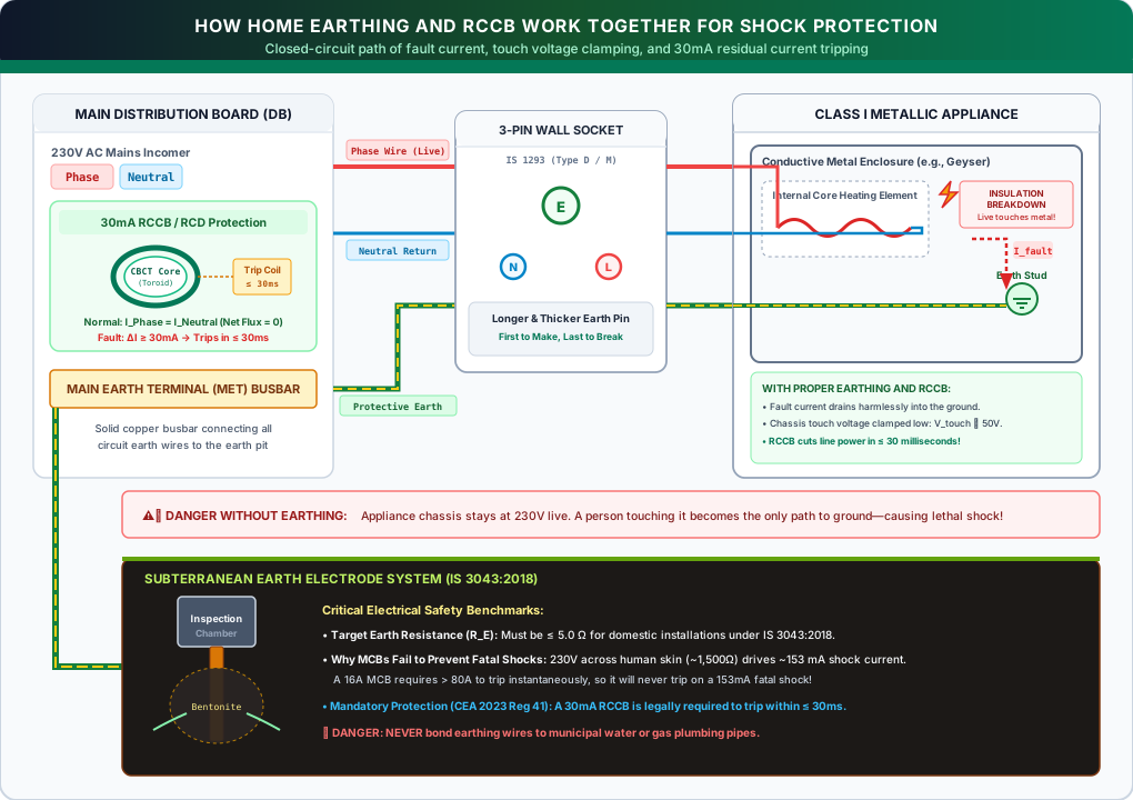
The Hazard of Class I Appliances
Household appliances are classified into distinct insulation categories under international electrotechnical standards:
- Class II (Double-Insulated) Appliances: An appliance should not be assumed to be Class II merely because of an outer plastic body. Class II equipment is engineered with supplementary or reinforced insulation to protect against electric shock and typically does not rely on a protective-earth connection. Always verify appliance classification through the manufacturer's markings (such as the concentric double-square symbol) and official instructions.
- Class I Appliances: Class I appliances have exposed conductive parts that are connected to a protective-earth conductor where required by their design (typical household examples include storage water geysers, washing machines, refrigerators, microwave ovens, electric irons, and desktop computer cabinets). If the basic insulation of an internal component degrades due to thermal stress, mechanical vibration, moisture ingress, or wear, an energized conductor can contact exposed conductive parts.
A phase-to-chassis insulation fault can make exposed metal parts dangerously live if the protective earth connection or automatic disconnection fails. If a person touches an energized conductive casing while in contact with the ground or other conductive elements, electric current can flow through the body, posing a severe risk of electric shock or cardiac ventricular fibrillation.
The Physics of Fault Current Dissipation & Touch Voltage
Protective earthing addresses this vulnerability by bonding all exposed conductive metal casings directly to a protective conductor (PE) network connected to the distribution board earthing terminal and earthing system.
When a phase-to-casing insulation fault occurs:
- Creating a Pre-Engineered Fault Path: The fault current does not have to wait for a human touch; it immediately surges into the protective earth conductor.
- Voltage Drop on Protective Conductor & Touch Voltage (Vtouch): The formula below provides a simplified illustration of the voltage drop across the protective conductor during a fault. It is important to note that this formula alone does not determine the actual touch voltage appearing on an appliance casing; actual touch voltage depends on the fault location, equipotential bonding, conductor impedance, and the earthing arrangement (such as TN vs. TT systems):
In an earthed installation, the protective conductor provides a dedicated fault path back toward the supply source. While a low-resistance bond helps suppress casing touch voltage compared to an unbonded chassis floating at full line voltage (230V), the metallic casing cannot be assumed to remain safe on its own in every installation. Actual conductor resistance and touch voltage vary widely based on circuit length, conductor sizing, termination quality, and the earthing system arrangement (TN vs. TT). Consequently, protective earthing alone is never a standalone life-safety guarantee; it must always be paired with an upstream protective device (such as an MCB or 30mA RCCB) engineered to achieve automatic disconnection of supply (ADS) within prescribed safety time limits.
Understanding the Return Path: TN vs. TT Systems
A common misconception is that fault current simply "disappears into the ground." In physics, all electric current must return to its source (the substation transformer secondary winding):
- In TN Systems (e.g., TN-S, TN-C-S): The consumer's protective earth (PE) conductor is bonded directly to the incoming utility supply neutral/earth conductor. The fault current returns primarily through this solid metallic pathway, resulting in a high fault current that quickly trips an MCB. The local earth electrode stabilizes the potential relative to earth, but is not the primary carrier of the return fault current.
- In TT Systems: The consumer's installation relies on an independent earth electrode pit with no metallic return conductor back to the substation. In this arrangement, fault current must travel from the local earth electrode through the mass of the soil to the utility transformer's grounding point. Because soil path impedance is typically several ohms or higher, fault currents in TT systems are often insufficient to trip an MCB quickly—making a sensitive Residual Current Device (30mA RCCB) essential to disconnect the circuit before dangerous touch voltages persist.
The Fundamental Limitation of Earthing Alone
A critical engineering truth that homeowners must recognize: protective earthing by itself does not stop current flow. Earthing does not possess switches, sensors, or moving mechanical parts; it is purely a passive metallic highway.
Earthing works strictly as a partner to upstream protective tripping devices (MCBs or RCCBs). Earthing creates the fault loop necessary to drive sufficient fault current; that current must then rapidly force the protective breaker to disconnect power before heat builds up or an electrocution occurs.
2. How Home Earthing Works: The Complete Circuit Loop
A residential earthing installation is not merely a rod in the ground; it is an engineered electrical protective network providing a continuous pathway from the appliance back through the distribution system:
- Appliance Metallic Chassis: Any Class I home appliance (refrigerators, washing machines, microwaves, water heaters) anchors an internal copper earth lead directly to its conductive outer shell.
- Internal Earth Bond to 3-Pin Plug (IS 1293 6A / 16A): The bond travels through the flexible appliance cord to connect specifically to the longer, thicker top pin of the three-pin plug.
- Longer Top Earth Pin into Wall Socket: Standard plug designs feature a longer top earth pin intended to facilitate the protective earth contact engaging before live pins mate during insertion and disengaging after live pins separate upon removal.
- Protective Earth (PE) Conductor in Branch Conduits: A continuous green or green-and-yellow insulated copper protective conductor—sized according to circuit loading, upstream overcurrent protection, and applicable wiring guidelines under IS 732—routes through wall conduits back to the distribution board.
- Distribution Board Main Earthing Terminal (MET) Busbar: All separate branch earth wires converge on a solid brass/copper grounding busbar, helping reduce potential differences across the home's grounded metalwork.
- Main Earthing Conductor & Earthing System: A dedicated protective earthing conductor—sized for mechanical protection and prospective thermal fault withstand in accordance with IS 3043—connects the MET busbar to the installation's earthing system (and to the utility neutral conductor in TN-C-S installations).
1. The Appliance Chassis Bonding
Inside any Class I appliance, an internal green-and-yellow conductor is bolted directly to the metal chassis using a dedicated terminal screw, often marked with the international earth symbol (⏚). A correctly installed and continuous protective-earth connection provides a fault-current path that helps protective devices disconnect the supply. Its effectiveness must be verified by appropriate electrical testing.
2. Three-Pin Plugs & Sockets (IS 1293:2019)
Under Bureau of Indian Standards specification IS 1293:2019 (Plugs and Socket-Outlets of Rated Voltage up to and including 250 Volts and Rated Current up to and including 16 Amperes), standard domestic plug configurations are specified primarily by electrical rating: 6 Amp / 250V (commonly referred to internationally as Type D) for lighting and light appliances, and 16 Amp / 250V (commonly referred to internationally as Type M) for heavy power equipment (geysers, air conditioners, heaters, and water pumps).
Key dimensional safety provisions defined in plug standards include:
- Greater Length of the Earth Pin: The top earth pin is physically longer than the live and neutral pins. In standardized 3-pin plug designs, this dimensional difference is intended to enable the protective-earth contact to engage before live pins mate during insertion, and disengage after live pins separate upon withdrawal. However, continuous shock protection during insertion and withdrawal also depends on socket construction, mechanical wear, and compliance with applicable standard dimensions (such as IS 1293).
- Greater Diameter of the Earth Pin: The earth pin has a significantly wider cross-sectional diameter. Under standard dimensional specifications, this difference in pin geometry ensures correct polarization, preventing a user from accidentally forcing the earth pin into live or neutral socket apertures.
3. The Protective Earth (PE) Conductor
Running through your home's conduits alongside phase and neutral cables is an insulated copper conductor (standardized as green or green-and-yellow). Required cross-sectional sizing depends on circuit load, prospective fault levels, and installation methods governed by IS 732:2019 (Code of Practice for Electrical Wiring Installations) and the National Electrical Code of India. In engineered installations, the required cross-sectional area is determined by the electrical designer based on upstream protective device characteristics, disconnection time, and thermal withstand capacity using the adiabatic equation (S = √(I2t) / k).
4. The Distribution Board (DB) Earth Busbar
In your main consumer unit or distribution board, all branch earth conductors converge at a solid brass or copper terminal bar called the Main Earthing Terminal (MET). This busbar provides an equipotential bonding connection that helps reduce potential differences between exposed grounded metal surfaces across the home during fault or transient conditions.
5. The Main Earthing Lead & Earth Pit
From the MET busbar, a dedicated main earthing conductor routes downward outside the building to the buried earth electrode system.
Under IS 3043:2018 (Code of Practice for Earthing), standard electrode types include:
- Pipe Electrodes: Perforated metal or galvanized pipe embedded vertically into the soil.
- Plate Electrodes: Metal plates installed vertically below permanent moisture level.
- Rod Electrodes: Driven or drilled solid steel core or copper-bonded steel rods installed with conductive backfill.
Note on Engineering Application: Specific electrode geometries, depths, backfill methods, and conductor cross-sections are governed by detailed design calculations and site conditions under IS 3043 and IS 732. They are not universal fixed dimensions for every home; the appropriate configuration must be evaluated by a qualified electrical engineer based on site-specific soil resistivity, prospective fault currents, and the system earthing arrangement (TT vs. TN). Applicable clauses and standard specifications can be referenced through the Bureau of Indian Standards (BIS) website or the BIS Standards Portal.
3. Common Signs of Possible Earthing Problems
An earthing failure is uniquely hazardous because, unlike a severed neutral or blown fuse that immediately stops an appliance from functioning, a broken protective-earth connection may not affect an appliance’s normal operation, which is why the fault can remain unnoticed until an electrical fault occurs. Your refrigerator continues to freeze food, your washing machine spins normally, and your water heater delivers piping hot water—all while operating in an ungrounded, potentially hazardous state.
Homeowners should monitor for these telltale indicators:
Sign 1: The "Tingling Sensation" or Micro-Shock from Appliance Bodies
If touching the metallic door handle of a refrigerator, the chrome tap connected to a geyser, or the unpainted metal screw on a desktop computer gives you a mild electric buzz or vibrating tingle—especially when barefoot—the protective ground circuit is severely compromised.
A mild tingle does not always mean a live phase wire is dead-shorted to the chassis. Modern digital electronics (computers, smart TVs, inverter appliances) contain Switch Mode Power Supplies (SMPS) with built-in Electromagnetic Interference (EMI) filter networks. These filters incorporate small safety capacitors connected between line conductors and chassis ground.
In a healthy system, minute filter leakage currents drain safely into the protective earth conductor. However, if the wall socket's earth connection is broken or floating, this leakage can cause a palpable touch voltage to appear on exposed conductive parts. While filter leakage current alone is often limited by capacitor design, any tingling or shock sensation from an appliance's exposed conductive parts is a warning sign of a possible electrical fault. Stop using the appliance, keep others away, and have a qualified electrician investigate the cause. Do not assume that the cause is a grounding fault until the installation and appliance have been tested.
Sign 2: Frequent Nuisance RCCB/RCD Tripping (or Failure to Trip)
If your Residual Current Circuit Breaker trips intermittently when appliances start up, or during periods of elevated humidity, it may indicate cumulative standing leakage, moisture ingress, an appliance defect, or another circuit fault; testing by a qualified electrician is needed to diagnose the exact cause. Conversely, if your RCCB never trips even when you depress its mechanical "T" (Test) button, the device's internal sensing core or mechanical latch may be inoperative, requiring immediate professional evaluation.
Sign 3: Audio Hum, Video Interference, and Ground Loops
Audiophiles, recording musicians, and home theater enthusiasts frequently encounter a persistent 50 Hz low-frequency hum or buzzing sound through amplified speakers. Known as a ground loop, this occurs when multiple interconnected devices have slightly differing ground reference potentials due to high-resistance earth wiring, causing small currents to circulate through audio shielding cables.
Sign 4: Elevated Neutral-to-Earth Voltage (VN-E)
In a theoretically balanced single-phase circuit, the voltage between Neutral and Earth at a wall socket is close to zero. In practice, Neutral-to-Earth voltage is not a fixed statutory number; it fluctuates depending on transformer distance, three-phase load unbalance across the utility feeder, and return path conductor resistance. If unexpected or fluctuating Neutral-to-Earth voltage is detected, have a qualified electrician inspect the installation to verify that neutral connections and grounding conductors are secure and undamaged.
Sign 5: Physical Corrosion or Dryness at the Earth Electrode Chamber
An outdoor earth pit requires periodic visual inspection. Visible signs of failure include:
- A severed or oxidized green earthing lead at the electrode lug.
- Severe galvanic corrosion eating away the clamp assembly.
- Parched, cracked earth around the pit casing during dry periods; soil resistivity depends on moisture content, soil composition, and temperature, which can significantly alter electrode performance.
4. Symptom-to-Action Diagnostic Matrix
Do not attempt to guess or self-diagnose electrical faults with improvised tests. Use this systematic reference to determine safe immediate actions and what diagnostic tests your certified electrician must perform:
| Observed Symptom | Potential Underlying Causes (Non-Definitive) | Immediate Homeowner Safe Action | Professional Diagnostic Step |
|---|---|---|---|
| Tingling or mild shock when touching refrigerator, geyser, or washer. |
• Disconnected or broken branch PE wire. • 2-pin plug used on Class I device via adapter. • Normal SMPS EMI filter leakage on ungrounded frame. • Incipient heating element insulation breakdown. |
Do NOT touch the appliance, plug, or wall socket. Switch off the wall switch (only if safely reachable without touching metalwork) or disconnect power from the distribution board's branch circuit breaker. Keep everyone away from the appliance until inspected by a licensed electrician. | Perform Protective Earth continuity testing to the DB busbar. Properly isolate sensitive electronic controls and perform insulation resistance testing on the isolated circuit/element. |
| RCCB trips every time a specific appliance is switched on. |
• Water ingress into geyser/pump terminal housing. • Neutral-to-Earth fault inside the appliance. • Deterioration in internal wiring or component insulation resistance. |
Leave that specific branch circuit breaker OFF. Do not bypass or bridge the RCCB under any circumstances. | Isolate live and neutral conductors; measure residual leakage with a calibrated clamp meter. Inspect terminal junction boxes for moisture or charring. |
| Frequent RCCB tripping during monsoon rain without obvious appliance fault. |
• Outdoor garden lighting or pump wiring moisture ingress. • Sub-distribution box water leakage. • Cumulative background standing leakage across older degraded PVC wires. |
Turn off external outdoor circuits at the sub-panel. Ensure consumer unit casing remains dry. | Perform instrument tripping tests on the RCCB using a dedicated RCD tester. Measure insulation resistance across isolated branch circuits to locate sections with moisture ingress. |
| Unusual or elevated Neutral-to-Earth voltage detected at wall sockets. |
• High-resistance earth connection. • Loose or corroded main neutral conductor at incomer. • Heavy single-phase load unbalance on distribution transformer. |
Do not rely on voltage stabilizers to mask wiring or neutral faults. Have a qualified electrician promptly inspect the main panel, incoming service neutral, and local earthing to determine whether the issue is a loose connection or supply-side unbalance. | The electrician selects appropriate diagnostic checks—such as verifying supply neutral and protective-earth continuity, tightening and torque-checking neutral connections, measuring earth-fault loop impedance where appropriate, and evaluating electrode resistance in accordance with the installation's earthing arrangement. |
| Appliance casing is severely live (causes muscular contraction / strong shock). | • Direct phase-to-chassis dead short coupled with a totally disconnected or severed earthing system. | CRITICAL SAFETY PROTOCOL: If the main distribution isolator switch can be reached safely without touching the live appliance, wet flooring, or any conductive metalwork, turn it OFF immediately. If approaching the panel poses any personal hazard, do not approach: immediately evacuate everyone from the room, keep the area clear, and summon emergency electrical or utility assistance. Never touch an electrocution victim or energized chassis with bare hands. | Emergency full-installation safety audit. Verify main earthing bonding, continuity, and replace failed circuit breakers. |
5. How Electricians Inspect and Test Earthing
Isolating the main earthing lead, opening distribution panels, or performing loop impedance measurements under energized conditions presents severe shock, arc-flash, and disconnection hazards. All electrical testing must be performed exclusively by a qualified professional using proper isolation procedures, calibrated test instruments, and appropriate personal protective equipment. Homeowners must never attempt these tests or open electrical panels.
A pervasive and perilous myth in residential maintenance is that earthing can be tested using an ordinary incandescent light bulb (connecting one wire to Phase and the other to Earth to see if the bulb lights up) or by touching an illuminated neon tester screwdriver to the wall socket's earth hole.
A standard 60-watt incandescent test bulb draws a nominal current of approximately 0.26 Amperes at 230V. Because this current is small, the bulb will illuminate even if earthing resistance has deteriorated to an unacceptable and hazardous resistance of 50 Ω or 100 Ω. A bulb test cannot evaluate loop impedance, disconnection times, or compliance with safety standards. Furthermore, performing an improvised test intentionally injects live current into building metalwork, creating a lethal shock hazard if earthing is compromised or an RCCB is absent. Never attempt or rely on DIY bulb tests.
Licensed electrical contractors and certified testing engineers utilize three rigorous, quantitative tests compliant with IS 732 and IS 3043:
Test 1: Protective Earth Continuity Testing
Using a calibrated Low-Resistance Digital Ohmmeter (delivering a test current of at least 200 milliamperes to break through light surface oxidation):
- The technician connects one lead to the Main Earthing Terminal (MET) at the distribution board and the other lead to the earth pin of every individual 3-pin wall socket and appliance metal casing.
- Engineering Evaluation: Continuity testing confirms that the protective conductor forms an unbroken metallic path back to the MET busbar. While a low resistance (often well under 1.0 Ω for typical short domestic branch runs) is expected, there is no single universal pass/fail figure; the measured resistance must be evaluated by the testing engineer against the expected theoretical resistance for the specific conductor cross-sectional area and run length. Unexpectedly high resistance points to loose terminal screws, corroded socket contacts, or damaged cabling.
Test 2: Earth-Fault Loop Impedance Testing (Zs)
Earth-fault loop impedance (Zs) is the total impedance encountered by a fault current traversing the complete loop from the supply transformer secondary winding, through the live service conductor, protective breaker, fault point, and returning back to the transformer neutral. In a TN system, this return path is formed predominantly by the low-impedance metallic protective conductor (PE / PEN); in a TT system, the return path includes the consumer's earth electrode, the ground soil mass, and the substation neutral earth electrode.
Using an electronic Loop Impedance Tester, the electrician measures total loop impedance (Zs) in ohms across the circuit.
Under Ohm's Law, the maximum fault current that can flow during a dead short is:
Where U0 is the nominal phase-to-earth line voltage (230V).
Under international standard IEC 60364-4-41 and national wiring practice (such as IS 732), socket circuits in TN systems are commonly designed to achieve automatic disconnection of supply within 0.4 seconds at 230V during a phase-to-earth fault.
Illustrative Example under Specific Assumptions: To understand how loop impedance relates to disconnection, consider a theoretical 230V branch circuit in a TN system protected by a standard Type-C 16A MCB conforming to IS/IEC 60898. Under standard product curves, the instantaneous magnetic trip band operates between 5× and 10× rated current (In). Under these specific assumptions, if evaluating the threshold prospective current often associated with instantaneous magnetic release (10 × In = 160A):
Important Engineering Note: This 0.4-second disconnection reference and 1.44 Ω figure represent an illustrative calculation under specific theoretical assumptions (a TN system, 230V nominal voltage, and a Type-C 16A MCB). They must not be treated as a universal pass/fail rule for all Indian domestic installations. Disconnection within required safety times depends on the specific device's published time-current characteristics, manufacturing tolerances, prospective fault level, and installation conditions; a prospective current alone does not guarantee a specific tripping speed without consulting the device curve.
Similarly, in TT systems, the conventional relation RA × IΔn ≤ 50V serves as a general engineering guideline for touch-voltage limitation under earth faults (relying primarily on a sensitive RCCB), rather than a single universal pass/fail test covering every operating condition.
Test 3: Earth Electrode Resistance Testing (RE - Fall of Potential Method)
To evaluate the resistance between the buried electrode and the surrounding soil mass, technicians use a specialized earth resistance tester employing established test methods such as the Fall of Potential Method:
- The main earthing lead is temporarily isolated from the distribution panel to avoid measuring parallel building bonding paths.
- Auxiliary potential and current reference probes are driven into the ground at calculated distances away from the earth electrode.
- The instrument circulates an alternating test current between the electrode and the outer current probe while measuring the voltage drop at the intermediate potential probe.
- Engineering Evaluation under IS 3043:2018: Acceptable earth electrode resistance depends on the earthing system arrangement (TT vs. TN-S / TN-C-S), soil characteristics, and upstream protective device coordination:
- In TN systems, disconnection safety is governed primarily by total Earth-Fault Loop Impedance (Zs) along metallic conductors, enabling overcurrent devices to clear faults rapidly.
- In TT systems, where fault current returns through the earth mass, keeping electrode resistance reasonably low minimizes ground potential rise, while an RCCB provides automated disconnection in coordination with touch-voltage limits (such as the general rule RA × IΔn ≤ 50V). Therefore, electrode condition and circuit loop impedance must be evaluated together in their specific engineering context.
No single measurement alone guarantees safety: an earth electrode can test at a pristine resistance, but if an interior wall terminal screw is loose, the socket inside your nursery has infinite impedance. Both the outdoor electrode system and interior circuit continuity must be certified together.
6. Earthing vs. MCB vs. RCCB/RCD: The Protection Trio Compared
One of the most dangerous misconceptions held by property owners is believing that having modern Miniature Circuit Breakers (MCBs) eliminates the need for proper earthing or an RCCB (Residual Current Circuit Breaker).
These three protective layers serve fundamentally different, non-interchangeable engineering roles. While property owners often confuse them or assume that having MCBs makes other protections unnecessary, each addresses a completely different physical hazard:
| Safety Device | Engineering Classification | Primary Protection Role | Typical Operating Threshold | Disconnection Action |
|---|---|---|---|---|
| Protective Earthing | Passive Metallic Pathway | Provides a low-impedance path to guide fault currents back to the source neutral, keeping casing touch voltage low. | Continuous passive conductor (evaluated alongside total loop impedance Zs) | None (Earthing carries fault current; it cannot mechanically break the circuit) |
| Miniature Circuit Breaker (MCB) | Overcurrent & Thermal Breaker | Protects home electrical cables and appliances from fire caused by thermal overloads and short circuits. | 6A to 63A (High current thresholds, e.g. 16A or 20A for inverter air conditioners) | Trips on massive overcurrents, but does not respond to milliampere-range human shock currents |
| Residual Current Circuit Breaker (RCCB) | Residual Current Protective Device (Earth-Leakage Protection) | Provides vital additional protection against electric shock from earth leakage and detects insulation degradation. | 30 mA for domestic personal shock protection (higher ratings, such as 100–300 mA, may be used for specific fire-protection or installation-coordination purposes where the design and applicable requirements call for them) | Standard product-standard maximum break times under specified laboratory test conditions per IS 12640 (Part 1):2024 / IEC 61008-1:2013: max 300 ms at 1× IΔn (30 mA), max 150 ms at 2× IΔn, and max 40 ms at 5× IΔn. (These figures are factory type-test limits under defined test parameters; actual in-service disconnection depends on fault magnitude, supply waveform, and device condition, and does not eliminate all shock hazards) |
Why an MCB Cannot Protect You from Fatal Electric Shock
An MCB is sized to protect copper building cables from overheating and catching fire. A typical domestic power circuit uses a 16 Amp or 20 Amp MCB.
If a human touches a live metal chassis, the electrical resistance of human skin and internal tissues under damp conditions is approximately 1,000 to 2,000 Ohms. Under 230V mains supply, the current forced through that person's body is:
This 153 mA figure is an illustrative calculation demonstrating the magnitude of potential shock current. In real-world accidents, the physiological impact, severity of injury, or cardiac effects depend on several variables—including the current path across the body, duration of contact, skin moisture, and individual physiological factors—rather than an assumed single outcome from current value alone. Crucially, to a 16 Amp MCB, an extra 0.153 Amps is completely invisible; the breaker perceives 0.153A as no different from a tiny 35-watt LED lamp being turned on.
Under normal single-person contact conditions, an MCB cannot be relied upon to provide personal shock protection. An MCB's thermal and magnetic trip mechanisms are engineered for high overcurrents (6A to 63A) to protect wiring from thermal overload and short circuits. Because the current flowing through a human body at 230V mains voltage is typically between 50 mA and 200 mA, it represents merely a fraction of an ampere—far below an MCB's minimum tripping threshold. Consequently, the MCB continues conducting current without opening, leaving personal shock protection dependent upon an earth leakage device (such as an RCCB) or an engineered low-impedance metallic fault loop that forces a dead short.
The Protection Role of the RCCB
An RCCB monitors the balance of currents passing through the active supply conductors (Phase and Neutral) using a sensitive Core Balance Current Transformer (CBCT) toroid:
- Under normal healthy operating conditions, the currents flowing through the phase and neutral conductors are equal and balanced, creating zero net magnetic flux in the sensing core (Φnet = 0).
- When some current returns through an unintended path (such as a protective earth conductor or through a person's body to ground) instead of the monitored neutral conductor, the phase and neutral currents become unequal.
- The RCCB detects this residual differential current, and its internal trip mechanism disconnects the circuit when its rated operating conditions are met (typically 30 mA for domestic life safety).
Under standard product specifications (IS 12640 (Part 1):2024 / IEC 61008-1:2013), maximum break times are verified under specific laboratory test conditions (such as limits up to 300 ms at 1× IΔn, 150 ms at 2× IΔn, and 40 ms at 5× IΔn). These defined test limits verify standard manufacturing performance under controlled laboratory setups; actual in-field disconnection speed varies with real-world fault magnitude and installation conditions. While an operational 30 mA RCCB significantly lowers the duration and physiological risk of severe shock, it does not provide absolute protection against every electric shock hazard. In particular, an RCCB cannot detect or protect against direct contact across Phase and Neutral conductors without leakage escaping to earth, nor can it eliminate the initial physiological shock sensation before the mechanical latch disengages.
7. When to Call a Licensed Electrical Contractor (Safety Protocols)
Residential electrical distribution boards carry high fault energies capable of severe arc-flash burns and lethal electrocution. Homeowners must never perform live internal distribution panel troubleshooting or unauthorized grounding modifications.
Non-Negotiable Red Flags Requiring Immediate Professional Service:
- Persistent Shock or Vibration: Any appliance whose metallic casing delivers a palpable shock or tingling sensation upon contact.
- Burning Smell or Discoloration: Any acrid ozone smell near the main breaker board, scorched plastic around 3-pin wall sockets, or buzzing/crackling sounds inside switchboards.
- The RCCB Refuses to Reset: If your RCCB trips and instantly snaps back off when you attempt to reset it, a persistent fault, leakage condition, or device problem may be present. Do not force the RCCB to stay on or repeatedly attempt to reset it. Keep the affected circuit off and contact a qualified electrician.
- Frequent Tripping During Inclement Weather: Indicates compromised underground conduit seals, external lighting water ingress, or wet electrical service penetrations.
In decades past, untrained handymen occasionally clamped electrical ground wires onto metallic municipal water pipes. Do not use water or gas piping as a substitute for a designed earthing electrode or protective-earth conductor. Required protective equipotential bonding of metallic services is a separate matter and must follow applicable wiring rules.
Modern residential plumbing extensively utilizes non-conductive plastic piping—such as CPVC, UPVC, and PEX. If an earthing wire is clamped to an isolated section of metal pipe that transitions into plastic plumbing, the pipe cannot dissipate fault current. Instead, the entire plumbing system—including shower heads, brass taps, and sinks—can become energized at 230V during a fault, creating an extreme electrocution hazard.
Important Distinction: Do not confuse this restriction with protective equipotential bonding. Wiring standards (such as IS 732) require extraneous metallic service pipes entering a building to be bonded to the Main Earthing Terminal (MET) to help mitigate dangerous potential differences between conductive metalwork. Equipotential bonding equalizes potentials for safety, but service piping must never serve as the installation's earthing electrode.
What Homeowners Can Safely Do:
- Perform Periodic Mechanical RCCB Trip Tests as per Manufacturer Instructions: Locate the RCCB in your distribution board and firmly depress the external test button marked "T" at the frequency recommended by the device manufacturer (manufacturers typically recommend testing monthly or quarterly). The switch handle should instantly snap down with a crisp mechanical click, cutting off power to the protected circuits. Push the handle firmly back up to reset. If the button does not trip the breaker, call a qualified electrician immediately to replace the defective unit. (Note: The test button verifies the internal mechanical and electrical tripping mechanism of the RCCB; it does not verify protective-earth continuity, earth-electrode resistance, or the complete installation's fault-loop performance).
- Inspect Outdoor Earth Chambers Visually: Ensure the concrete inspection box is accessible, undamaged, and that the top cover is firmly seated. Never attempt to handle earth electrodes, live terminals, or internal panel wiring yourself.
8. Statutory Standards & Regulatory Framework in India
For homeowners, building managers, and electrical contractors in India, electrical safety and earthing are governed by statutory regulations and national engineering standards:
Central Electricity Authority (Measures Relating to Safety and Electric Supply) Regulations, 2023 (and Amendments):
- Regulation 43 (Connection with earth): Specifies statutory requirements for connecting non-current-carrying metal parts and equipment casings to earth. It establishes provisions governing consumer installation earthing, fault loop impedance, and coordination with protective devices to achieve automatic disconnection.
- Regulation 44 (Residual Current Device): Specifies the requirement for residual current device (RCD) protection in electrical installations to disconnect the supply under fault or leakage conditions. For domestic installations, it requires the provision of an RCD with a rated residual operating current not exceeding 30 mA, subject to the conditions, installation arrangements, and statutory exceptions laid down in the Regulations.
- Official Gazette Notifications & 2026 Amendment: The Central Electricity Authority periodically updates these regulations via official Gazette notifications—such as the CEA (Measures Relating to Safety and Electric Supply) Amendment Regulations, 2026, which incorporates specialized safety frameworks for Battery Energy Storage Systems (BESS under Chapter XA) and updates applicable standards. For complete, authoritative clauses and legal applicability, always consult the official Gazette publications on the Central Electricity Authority (CEA) Website.
Bureau of Indian Standards IS 3043:2018 (Code of Practice for Earthing):
- The primary national engineering code for earthing design. It provides design procedures, standard electrode configurations (pipe, plate, and rod electrodes), soil resistivity testing methods, and rules for both TN and TT earthing arrangements. Specific dimensions and materials must be selected based on prospective fault currents and soil conditions per the relevant clauses of IS 3043:2018. For official Indian Standards, including applicable clauses and revisions, consult the Bureau of Indian Standards (BIS) website or the BIS Standards Portal. Search by the relevant IS standard number to locate available standard details and revision information.
Bureau of Indian Standards IS 12640 (Part 1):2024 / IEC 61008-1:2013:
- Residual Current Operated Circuit-Breakers without Integral Overcurrent Protection for Household and Similar Uses (RCCBs) - Part 1: General rules. Specifies construction, operating characteristics, and standardized type-test break time limits for domestic residual current devices.
Bureau of Indian Standards IS 1293:2019 (Plugs and Socket-Outlets):
- Plugs and Socket-Outlets of Rated Voltage up to and including 250 Volts and Rated Current up to and including 16 Amperes - Specification. Specifies dimensional, constructional, and safety requirements for domestic plugs and socket-outlets (covering Type D 6A and Type M 16A configurations), including protective earthing pin dimensions intended to establish earthing continuity.
Bureau of Indian Standards IS 732:2019 (Code of Practice for Electrical Wiring Installations) & NEC 2023:
- Provides national wiring design guidelines, protective conductor identification (green / green-yellow), conductor sizing methodologies based on thermal withstand, and maximum disconnection times for low-voltage installations.
Summary Checklist for Homeowners
To ensure your home remains safe, resilient, and fully compliant with modern electrical safety codes, verify these core benchmarks:
- All Class I appliances (geysers, washing machines, refrigerators, microwaves) are connected via proper 3-pin plugs into matching earthed wall sockets. Never use two-pin ungrounded cheater adapters.
- A 30mA RCCB / RCBO is installed in the main distribution board and trips reliably when the mechanical "T" (Test) button is pressed at the frequency recommended by the device manufacturer.
- No tingling sensation or vibration is detectable when touching any metal appliance casing while barefoot.
- Protective earthing conductors are continuous copper, sized appropriately for circuit loads per IS 732 guidelines, running through all conduits back to the distribution board earth busbar.
- The outdoor earth pit is constructed with an approved electrode per IS 3043, periodically verified by a qualified professional.
- Water plumbing pipes and gas pipes are not used as a substitute for a designed earthing electrode or protective-earth conductor, while required protective equipotential bonding follows applicable wiring rules.
- Periodic electrical safety inspections are arranged at intervals recommended by applicable local requirements and a qualified electrical professional—or arranged sooner if shocks, repeated tripping, damaged wiring, water ingress, or other warning signs are noticed.
References & Official Guidelines
For technical standards, statutory safety regulations, and official engineering codes, consult the following authoritative resources:
- Central Electricity Authority (CEA) — Safety and Electric Supply Regulations, 2023 (as amended) — Official statutory regulations published under Gazette of India, Ministry of Power. Statutory provisions for residual current device protection under Regulation 44 and connection with earth under Regulation 43.
- Bureau of Indian Standards (BIS) — IS 3043:2018 (Code of Practice for Earthing) — National standard specification for pipe, rod, and plate earthing electrodes, soil resistivity evaluation, and chemical backfill compounds.
- Bureau of Indian Standards (BIS) — IS 12640 (Part 1):2024, RCCBs — Official BIS publication describing residual-current circuit-breakers without integral overcurrent protection, including their safety function and testing requirements.
- Bureau of Indian Standards (BIS) — IS 1293:2019, Plugs and Socket-Outlets — Official BIS product manual for household plugs and socket-outlets rated up to 250 V and 16 A.
- Bureau of Indian Standards (BIS) — IS 732:2019, Code of Practice for Electrical Wiring Installations — BIS reference document describing the scope of this standard for electrical installation design, selection, erection, and verification.
- International Electrotechnical Commission (IEC) — IEC 60364-4-41 — Low-voltage electrical installations – Part 4-41: Protection for safety – Protection against electric shock.
- Health and Safety Executive (HSE UK) — Electrical Safety Guidelines & RCDs — Technical guidelines on residual current devices, earthing integrity, and low-voltage electrical safety.
Conclusion
Residential electrical earthing is not an optional accessory or a passive rod in the ground—it is an engineered electrical safety loop designed to partner with modern circuit protective devices. When installed correctly with continuous protective conductors, verified low-impedance pathways, and paired with a functioning 30mA RCCB, earthing forms your household's first and most reliable defense against dangerous touch voltages, equipment degradation, and fatal electric shocks.
Never ignore warning signs like tingling sensations, nuisance RCCB trips, or dry, corroded outdoor earth pits. Conduct regular periodic mechanical test button checks on your RCCB as recommended by the manufacturer, and schedule certified electrical inspections to ensure your home's earthing system remains resilient, code-compliant, and fully protective.