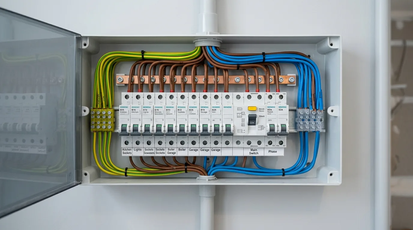
Every modern household relies on an unseen electrical distribution network operating behind concrete walls and inside distribution boards. Whenever you switch on an air conditioner, plug in an electric vehicle, or run a high-power kitchen appliance, electrical current flows through specific branch circuits protected by miniature circuit breakers (MCBs).
Yet, for many homeowners and renovators, electrical planning remains an afterthought. Overloading circuits, pairing oversized circuit breakers with undersized copper wires, or miscalculating the home's total electrical capacity can lead to frequent nuisance tripping, voltage fluctuations, premature appliance failure, and severe electrical fire hazards.
This technical guide explains how residential electrical loads are calculated, how power is safely distributed into branch circuits, how MCBs function, and how to coordinate conductor sizes with protective devices under applicable electrical safety codes.
1. Connected Load vs. Maximum Demand: The Critical Distinction
Before calculating branch circuits, homeowners must understand the fundamental difference between Connected Load and Maximum Demand (simultaneous peak load). Confusing these two figures often leads either to over-designed, expensive electrical service connections or to dangerous undersizing.
| Parameter | Connected Load (Total Nameplate Watts) | Maximum Demand (Peak Operational Demand) |
|---|---|---|
| Engineering Definition | The aggregate continuous rated power (in Watts or kW) of all permanently connected appliances and lighting fixtures, combined with standardized planning allowances for convenience socket outlets. | The highest actual electrical power drawn from the grid by the household during any single measurement window (typically 15 or 30 minutes). |
| Simultaneity Assumption | Assumes a theoretical worst-case benchmark where all connected appliances and assigned socket planning allowances operate concurrently at full rating. | Recognizes realistic domestic usage patterns where only a subset of total installed appliances operate at the same instant. |
| Primary Application | Used by distribution utilities to evaluate aggregate connected hardware capacity and verify regional building electrical sanction thresholds. | Governs the sizing of the main service cable, main distribution breaker, utility contract sanction load, and transformer provisioning. |
| Calculation Metric | Calculated by summing fixed appliance nameplate wattages and designated socket design allowances: Total Watts ÷ 1,000. | Estimated by applying an installation Demand Factor: Estimated Maximum Demand = Connected Load × Demand Factor. |
Understanding Demand Factor, Diversity Factor, and Simultaneity Factor
In residential electrical planning discussions, the terms Diversity Factor, Demand Factor, and Simultaneity Factor are frequently confused. In rigorous electrical engineering standards (such as IEC 60050 and IS 732), each has a distinct mathematical definition and load basis:
Demand Factor (always ≤ 1.0): The ratio of the coincident maximum electrical demand of an installation to its total connected load.
Demand Factor = Coincident Maximum Demand ÷ Total Connected LoadBecause a household never operates every single connected appliance and socket at maximum capacity simultaneously, the actual peak demand is a fraction of total connected load.Diversity Factor (always ≥ 1.0): The ratio of the sum of individual non-coincident maximum demands of various sub-circuits (or individual consumers) to the coincident maximum demand of the entire group.
Diversity Factor = ∑ (Individual Maximum Demands) ÷ Coincident Maximum Demand of the Entire GroupBecause peak demands of different circuits occur at different hours of the day (e.g., water heating peaks in the morning, air conditioning peaks during hot afternoons or night), the sum of individual peaks exceeds the simultaneous system peak, resulting in a Diversity Factor greater than 1.0.Simultaneity Factor (ks, always ≤ 1.0 per IEC 60050 / IS 732): The ratio of the coincident maximum demand of a group of circuits to the sum of the individual maximum demands of those circuits (the mathematical reciprocal of the diversity factor evaluated on the same load basis).
Simultaneity Factor (ks) = Coincident Maximum Demand ÷ ∑ (Individual Maximum Demands) = 1 ÷ Diversity FactorWhile Demand Factor relates coincident peak demand directly to *total connected nameplate load*, Simultaneity Factor specifically relates coincident peak demand to the *sum of individual circuit maximum demands* within a distribution group.
For example, in a hypothetical house with 10 kW of connected equipment, applying an illustrative hypothetical demand factor of 0.50 yields an estimated coincident peak demand of approximately 5.0 kW. This distinction prevents distribution companies from over-sizing transformers while helping consumers understand billing parameters (for details on how peak demand is registered on your meter, see our comprehensive guide on reading digital and smart electricity meters).
2. Calculating Total Connected Load from Home Appliances
To determine your home's total connected load, inventory each appliance, noting its continuous rated power in Watts (W) or kilowatts (kW) from its rear specification nameplate or manufacturer manual.
Standard Residential Appliance Wattage Benchmarks
The table below outlines representative wattage ranges for typical household electrical loads across modern single-phase (230V) installations:
| Appliance Category | Representative Power Rating (Watts) | Approximate Operating Current (@ 230V)* | Typical Branch Allocation (Subject to Sizing) |
|---|---|---|---|
| LED Ceiling / Downlight | 7 W – 15 W | ~0.03 A – 0.07 A | Shared Lighting Sub-Circuit |
| BLDC Energy-Saving Ceiling Fan | 28 W – 35 W | ~0.12 A – 0.15 A | Shared Lighting & Fan Circuit |
| Conventional Induction Ceiling Fan | 70 W – 80 W | ~0.30 A – 0.35 A | Shared Lighting & Fan Circuit |
| Refrigerator (250L – 350L Inverter) | 100 W – 180 W (running) | ~0.5 A – 0.8 A | General Convenience Socket Circuit |
| Smart TV & Soundbar | 80 W – 160 W | ~0.35 A – 0.70 A | General Convenience Socket Circuit |
| Automatic Washing Machine | 350 W (wash) / 1,800 W (with water heater) | ~1.5 A – 8.0 A | Dedicated Appliance Power Circuit |
| Microwave Oven | 1,200 W – 1,500 W | ~5.2 A – 6.5 A | Dedicated Kitchen Power Circuit |
| Storage Water Heater (Geyser, 15L – 25L) | 2,000 W – 3,000 W | ~8.7 A – 13.0 A | Dedicated Water Heating Circuit |
| Split Air Conditioner (1.5 Ton, Inverter) | 1,200 W – 1,600 W (rated max) | ~5.2 A – 7.0 A | Dedicated HVAC Branch Circuit |
| Induction Cooktop / Hob | 1,800 W – 2,200 W | ~7.8 A – 9.6 A | Dedicated Cooking Power Circuit |
| Electric Iron / Steam Press | 1,000 W – 1,600 W | ~4.3 A – 7.0 A | Power Socket Circuit |
(Note: While nameplate wattage provides the foundation for connected load calculations, calculating ongoing monthly consumption in kilowatt-hours requires factoring in daily runtime hours; refer to our guide on how to calculate electricity consumption in kWh for operating cost formulas).
3. How Circuits Are Divided: The Logic of Sub-Circuit Distribution
Connecting an entire floor or multiple high-draw appliances to a single pair of conductors creates hazardous electrical bottlenecks. In compliant electrical installations, power is distributed from the main consumer unit into separate Final Sub-Circuits (Branch Circuits) to limit continuous thermal stress on cables, provide operational redundancy so a fault in one zone does not black out the entire home, and prevent heavy motor inrush from causing lighting voltage dips.
Functional Sub-Circuit Allocation Principles
Rather than relying on universal rules, sub-circuit design is determined by applicable wiring standards (such as IS 732:2019), equipment power ratings, duty cycles, and local engineering requirements:
1. Lighting and Low-Power Fan Sub-Circuits
- Planning Conventions vs. Modern Standards: In traditional Indian building practice (such as legacy CPWD architectural norms), planners historically grouped lighting points to an informal benchmark of approximately 800 Watts or 8 to 10 points per circuit. However, modern statutory design under IS 732:2019 does not enforce arbitrary universal point caps. Instead, each lighting loop is designed based on actual nameplate LED wattage, continuous operational duty, and circuit route distance.
- Engineering Sizing Considerations: Because continuous running current on LED lighting loops is very modest (often under 1 to 2 Amperes), conductor sizing is governed primarily by mechanical robustness and voltage drop limits over the circuit distance (such as the recommended ≤ 3% guideline for lighting circuits in IS 732:2019 Table G.52.1), rather than thermal ampacity. The protective MCB rating must be coordinated strictly to satisfy Ib ≤ In ≤ Iz after accounting for grouping derating factors along the conduit route.
- Loads Served: Fixed ceiling lights, decorative wall sconces, exhaust fans, and ceiling fans.
2. General Convenience Socket Sub-Circuits
- Planning Conventions: General-purpose 6A/16A socket outlets intended for portable household appliances (televisions, computer workstations, mobile chargers, floor lamps) are grouped into dedicated convenience loops separated from lighting.
- Engineering Sizing Considerations: Socket circuits encounter unpredictable, intermittent plug loads. Conductor sizing and breaker protection must be designed using applicable installation reference methods and derating factors. When multiple socket circuits are bunched inside a shared conduit or routed through hot ceiling slabs, the cable's safe permissible ampacity (Iz) drops significantly. A qualified electrical contractor must verify that the chosen breaker rating (In) does not exceed the derated continuous capacity of the conductor along its entire physical run.
3. High-Draw Power Sub-Circuits (Independent Branch Runs)
Depending on appliance ratings, manufacturer instructions, and applicable wiring standards (such as IS 732), major high-draw appliances are often provided with dedicated branch circuits directly from the distribution board:
- Air Conditioners (Split Units): Depending on cooling capacity and motor ratings, individual circuits are commonly provided. Conductor cross-section is sized for compressor continuous running current, motor start-up inrush, and circuit route length to comply with recommended voltage-drop limits (such as the ≤ 5% guideline for power/motor circuits in IS 732:2019 Table G.52.1).
- Storage Water Heaters (Geysers): Because water geysers may draw sustained current during a heating cycle, an independent branch circuit is often provided. Sizing accounts for terminal connection heating, duty characteristics, and cable derating inside damp bathroom conduit routes.
- Kitchen Power Circuits (Microwave, Oven, or Induction): High-power culinary appliances draw sustained currents and generate localized ambient heat. Separate or dedicated branch circuits are often considered depending on equipment wattage and kitchen ambient temperatures.
- Electric Vehicle (EV) Home Chargers (3.3 kW to 7.4 kW): Dedicated heavy-duty circuits engineered strictly to the EVSE manufacturer's specifications and local distribution utility regulations, accommodating continuous maximum load over 6 to 10 consecutive hours.
4. Understanding the MCB: Working Principle, Tripping Curves, and Overload Protection
The Miniature Circuit Breaker (MCB) is an automatically operated electromechanical switch designed to protect an electrical circuit from damage caused by overcurrent (overloads and short circuits).
Unlike legacy rewirable ceramic porcelain fuses—which required manual wire replacement and posed severe fire and electrocution risks—an MCB can be easily reset with a toggle switch once the fault is cleared.
Dual Tripping Mechanisms: Thermal vs. Magnetic
An MCB provides two entirely distinct protection mechanisms inside a single sealed housing:
Thermal Protection (Sustained Overload):
- How it works: Electrical current passes through an internal bimetallic strip made of two bonded metals with differing thermal expansion rates.
- Reaction time: When circuit current exceeds the breaker's nominal rating by a modest margin (e.g., drawing 22 Amps through a 16A breaker), the bimetallic strip gradually heats, bends, and unlatches the mechanical trip mechanism.
- Purpose: Prevents cables inside walls from slowly cooking, degrading their PVC insulation, and causing structural fires over hours of sustained minor overload.
Magnetic Protection (Instantaneous Short-Circuit):
- How it works: In the event of a dead short circuit (such as a direct short between live phase and neutral conductors), current instantaneously spikes to hundreds or thousands of Amperes.
- Reaction time: This explosive current surge generates an intense magnetic field inside an internal electromagnetic solenoid, rapidly unlatching the contacts under electromagnetic interruption thresholds specified in standards such as IS/IEC 60898-1.
- Purpose: Extinguishes catastrophic short circuits before electrical cables explode or melt inside conduits.
MCB Tripping Characteristics (Curves B, C, and D)
Circuit breakers are categorized by their instantaneous magnetic tripping thresholds under standard specifications (such as IS/IEC 60898-1:2015 Clause 5.3.5):
| MCB Tripping Curve | Magnetic Tripping Multiplier | Intended Load Application | Residential Suitability |
|---|---|---|---|
| Type B Curve | Trips instantaneously at 3 to 5 times nominal rated current (In). | Purely resistive loads with minimal or no switching inrush surges: domestic electric heaters, incandescent lamps, and circuits with longer conductor runs. | Well-suited for residential lighting loops and resistive heating loads where lower earth fault loop impedance allows sensitive, fast disconnection. |
| Type C Curve | Trips instantaneously at 5 to 10 times nominal rated current (In). | Inductive motor loads with moderate transient inrush currents: residential air conditioners, refrigerators, washing machine motors, and LED driver banks. | Commonly specified for residential power circuits and motor-driven appliances, handling normal start-up surges without nuisance tripping. |
| Type D Curve | Trips instantaneously at 10 to 20 times nominal rated current (In). | Heavy industrial equipment with severe inrush spikes: large industrial transformers, industrial motors, and X-ray machinery. | Generally inappropriate for standard domestic branch circuits, as its high magnetic threshold requires extreme fault currents to trip instantly that domestic circuits may not produce. |
How MCB Tripping Curve is Actually Selected: Key Design Dependencies
Selecting whether to install a Type B, Type C, or Type D breaker is never a matter of guesswork or personal preference. Under national and international electrical standards (such as IS 732 and IS/IEC 60898-1), breaker curve selection is governed by three rigorous engineering criteria:
- Load Characteristics & Inrush Multipliers: Different appliances exhibit radically different current profiles upon startup. Purely resistive appliances (water geysers, electric kettles, radiant heaters) draw negligible start-up surge, making Type B suitable. Conversely, inductive motor-driven equipment (refrigerator compressors, split air conditioners, water pumps, power tool motors) can draw transient start-up inrush currents between 3 and 8 times their continuous running current. A sensitive Type B breaker could experience nuisance tripping each time a compressor kicks on, whereas a Type C breaker safely tolerates these brief normal motor transients.
- Earthing Arrangement & Disconnection Times: Required disconnection times depend on the applicable wiring standard, circuit characteristics, and earthing arrangement. TN and TT systems can have different requirements (for example, standards such as IEC 60364-4-41 and IS 732 specify distinct disconnection-time limits for 230V AC supplies); therefore, the designer must verify the actual site-specific earthing arrangement and protective-device performance rather than assume a universal disconnection time. Because Type C breakers require higher instantaneous magnetic tripping current (5 × In to 10 × In) compared to Type B (3 × In to 5 × In), the maximum allowable circuit earth fault loop impedance (Zs) for a Type C breaker is substantially lower (Zs ≤ U0 ÷ Ia). On long cable runs where conductor resistance increases loop impedance, a Type C breaker might fail to achieve fast magnetic disconnection, obliging the designer to either upsize the conductor cross-section, select a Type B breaker, or incorporate residual current protection.
- Prospective Fault Current & Protective Discrimination: The breaker's magnetic curve must be coordinated with upstream distribution devices (discrimination/selectivity) so that a local branch fault trips only the relevant branch breaker, leaving the main incomer energized.
Essential Technical Ratings on an MCB Faceplate
When inspecting a quality residential MCB, look for these standardized markings:
- Nominal Current Rating (e.g.,
C16orB10): Indicates a Type C or Type B tripping curve with a nominal continuous current carrying capacity of 16A or 10A. - Rated Operating Voltage (e.g.,
240V / 415V ~): Standard single-phase and three-phase AC operating limits. - Rated Breaking Capacity (e.g.,
6000or10000inside a rectangular box): The maximum prospective short-circuit fault current (in Amperes) the breaker can safely interrupt without disintegrating or causing an external fire. While 6,000A (6 kA) and 10,000A (10 kA) ratings are common in domestic installations under IS/IEC 60898-1, the required breaking capacity is governed by the actual prospective short-circuit current (PSCC) at the distribution board, which depends on transformer proximity and supply line impedance.
5. The Golden Engineering Rule: Coordinating Wire Size, Current, and MCB Rating
A widespread and dangerous misconception among homeowners is that an MCB is chosen to protect the television, air conditioner, or washing machine.
An MCB is installed primarily to protect the copper conductor inside your wall from overheating and igniting an electrical fire.
If an appliance develops an internal fault and demands 30 Amperes through a thin 1.5 mm² wire protected by an oversized 32A breaker, the breaker will not trip. Instead, the 1.5 mm² wire inside your conduit will heat to over 150°C, melt its insulation, and potentially spark an in-wall structural fire.
The Standard Coordination Inequality
In professional electrical design (governed by standards such as IEC 60364 and IS 732), circuit sizing must strictly satisfy this three-part coordination rule:
Where:
- Ib (Design Current): The actual operational current drawn by the appliances connected to that circuit.
- In (MCB Rating): The nominal rated current of the protective miniature circuit breaker.
- Iz (Cable Current Capacity / Ampacity): The maximum continuous permissible current the conductor can carry safely under its specific installation and temperature conditions.
Why Wire Sizes and MCB Ratings Cannot Be Selected from Generic Charts
In informal home building, installers frequently rely on rule-of-thumb sayings like "use 1.5 mm² for lights and 2.5 mm² with a 16A breaker for all sockets." In professional electrical engineering, such generic pairing charts are considered fundamentally unsafe and technically invalid.
Under established standards (such as IS 732:2019 and IEC 60364-5-52), the safe current-carrying capacity (effective ampacity, Iz) of an electrical conductor is not an inherent static number printed on the cable drum. Instead, every cable cross-section and its corresponding protective circuit breaker must be systematically determined through a multi-step engineering workflow:
The 5-Step Cable and Protection Sizing Workflow (IS 732 / IEC 60364)
Determine Circuit Design Operating Current (Ib): The electrical engineer calculates the maximum steady-state current expected under normal operating conditions based on the connected appliances, power factor, and applicable diversity factors.
Identify Installation Reference Method (Method A, B1, B2, C, etc.): Heat dissipation depends heavily on how the cable is physically routed. Per IS 732 Table 15, insulated single-core conductors enclosed in surface-mounted conduit on a wall (Method B1), embedded directly inside masonry plaster (Method B2), or clipped directly to a wooden batten (Method C) dissipate heat at radically different rates. A cable sealed inside thermal insulation or masonry runs much hotter than one in free air.
Apply Environmental and Grouping Derating Factors (Ca × Cg): The nominal tabulated ampacity (It) at standard reference conditions (typically 30°C) must be adjusted using statutory correction multipliers:
- Ambient Temperature Correction Factor (Ca): When conduits pass through hot ceiling plenums, attics, or exterior walls in tropical Indian summers where ambient temperatures exceed 40°C to 45°C, allowable current drops significantly.
- Grouping Correction Factor (Cg): When multiple energized branch circuits share the same conduit or trunking, mutual thermal interaction and restricted heat dissipation reduce conductor ampacity. The applicable derating factor varies depending on the installation method, number of grouped circuits, conduit fill, and thermal conditions according to applicable standard tables (such as IS 732 / IEC 60364-5-52).
- The effective continuous safe capacity becomes:
Iz = It × Ca × CgThe protective breaker rating (In) must strictly satisfy: Ib ≤ In ≤ Iz. If Iz falls below In due to severe derating, the conductor will overheat under load without the breaker ever tripping.Verify Recommended Voltage Drop Limits (IS 732 Table G.52.1): A cable might satisfy continuous thermal ampacity (Iz) over a short run, but on longer circuit runs (e.g. distant outdoor lighting, motor pumps, or air conditioner feeds), conductor resistance causes excessive voltage drop. Under IS 732:2019 Informative Annex G (Table G.52.1), recommended design guidelines for installations supplied from public low-voltage networks advise:
- Lighting Circuits: Recommended design limit of ≤ 3% (e.g., ≤ 6.9V on a nominal 230V single-phase supply) to prevent visible lamp flickering and driver stress.
- Other Uses (Power Sockets, Heating, Motor-Driven Appliances): Recommended design limit of ≤ 5% (e.g., ≤ 11.5V on a nominal 230V single-phase supply) to prevent motor stall, compressor overheating, and contactor chattering. If calculated voltage drop exceeds these recommended thresholds, the engineer must increase the cable cross-section to the next standard commercial size.
Verify Earth Fault Loop Impedance (Zs) & Short-Circuit Withstand (k²S² ≥ I²t): The conductor size and circuit path must ensure that in the event of an earth fault or short circuit:
- The total loop impedance is low enough to achieve required disconnection times under the applicable earthing arrangement (e.g., within 0.4 seconds for 230V final circuits in TN systems, or via sensitive RCD protection where higher impedance in TT systems restricts earth fault currents).
- The conductor can thermally withstand the intense fault energy (let-through energy I²t) cleared by the breaker before insulation degrades, governed by the adiabatic equation k²S² ≥ I²t.
Key Rule for Homeowners: The conductor cross-section and protective-device rating must be selected using the applicable wiring standard, installation method, corrected current-carrying capacity, voltage-drop limits, and fault-protection requirements. No single wire-size and MCB combination is suitable for every installation. Because these interdependent engineering checks require technical calculations, always rely on certified design by a licensed electrical professional.
6. Worked Example: Hypothetical 2BHK Residential Home
To understand how connected load calculations translate into branch circuits and panel hardware, examine this realistic planning scenario for a standard two-bedroom residential apartment (230V Single-Phase supply).
Step 1: Complete Household Connected Load Audit
In electrical engineering practice, appliances in a connected load calculation fall into two distinct planning categories:
- Fixed Dedicated Equipment (Nameplate Ratings): Appliances such as storage water geysers (2,000 W), inverter air conditioners (1,450 W rated), washing machines (1,800 W), and microwave ovens (1,300 W) have explicit manufacturer nameplate specifications and are tabulated directly at their rated continuous wattage.
- General Convenience Socket Outlets (Planning Allowance): Unlike fixed equipment, convenience 6A socket points do not have static continuous loads; plugged-in devices change constantly from a 10W smartphone charger to a 60W television or 15W Wi-Fi router. For this illustrative example, an assumed planning allowance of 100 W per general socket point is used. This is a modelling assumption, not a universal requirement under IS 732 or the National Building Code.
The table below summarizes the total connected load for this illustrative 2BHK residence:
| Load Item Description | Quantity | Unit Watts | Subtotal Connected Load (Watts) |
|---|---|---|---|
| LED Lighting Points (Living, Bedrooms, Kitchen, Baths) | 18 | 12 W | 216 W |
| BLDC Ceiling Fans | 4 | 32 W | 128 W |
| General Convenience Sockets (TV, Chargers, Router) | 8 | 100 W (allowance) | 800 W |
| Refrigerator (Inverter) | 1 | 150 W | 150 W |
| Washing Machine (Front-Load with heater) | 1 | 1,800 W | 1,800 W |
| Microwave Oven | 1 | 1,300 W | 1,300 W |
| Storage Water Geyser (Bathroom 1) | 1 | 2,000 W | 2,000 W |
| Storage Water Geyser (Bathroom 2) | 1 | 2,000 W | 2,000 W |
| Split AC (1.5 Ton Inverter - Master Bedroom) | 1 | 1,450 W | 1,450 W |
| Split AC (1.5 Ton Inverter - Living Room) | 1 | 1,450 W | 1,450 W |
| Total Connected Load (All Installed Appliances) | 11,294 Watts (11.29 kW) | ||
Step 2: Estimating Peak Coincident Demand (Hypothetical Textbook Scenario)
For this illustrative example, assume a hypothetical demand factor of 0.50. The estimated coincident demand is therefore:
This assumption is used only to demonstrate the calculation and is not a recommended design factor for an actual residence.
At a nominal single-phase voltage of 230V AC with an assumed power factor of 0.95:
Step 3: Illustrative Distribution Board Schedule (Functional Partitioning Model)
To safely partition and balance these loads, the consumer unit is organized into dedicated sub-circuits.
| Sub-Circuit ID & Purpose | Connected Load (Design Watts) | Calculated Operating Current (Ib @ 230V) | Engineering Design & Protection Criteria |
|---|---|---|---|
| Circuit 1: Lighting & Fans (Living, Dining, Balcony) | ~180 W | ~0.8 A | Continuous low current; conductor sizing is governed primarily by mechanical robustness and voltage drop limits (≤ 3%), with protective device coordinated per Ib ≤ In ≤ Iz. |
| Circuit 2: Lighting & Fans (Bedrooms & Bathrooms) | ~164 W | ~0.75 A | Segregated from Circuit 1 for operational redundancy; prevents total apartment darkness during a local lighting fault. |
| Circuit 3: General Convenience Sockets & Refrigerator Point | ~950 W (800 W socket allowance + 150 W refrigerator) | ~4.3 A (intermittent & continuous) | Feeds living and bedroom portable plug loads alongside the continuous food refrigerator supply point; grouping derating must be verified where circuits share conduits. |
| Circuit 4: Kitchen Counter Power Sockets | ~1,300 W | ~6.0 A | Dedicated power loop for culinary heating appliances; thermal derating required due to elevated ambient temperatures in kitchen areas. |
| Circuit 5: Balcony Utility (Washing Machine) | ~1,800 W | ~8.2 A | Dedicated appliance circuit; protective device tripping characteristic must tolerate wash motor start-up transients without nuisance tripping. |
| Circuit 6: Bathroom 1 Water Geyser | 2,000 W | ~9.1 A | May draw sustained current during a heating cycle; independent branch circuit often provided to isolate high heating current from general socket circuits. |
| Circuit 7: Bathroom 2 Water Geyser | 2,000 W | ~9.1 A | Independent circuit; isolates water heating load from Bathroom 1 to avoid excessive thermal stress on a shared circuit. |
| Circuit 8: Master Bedroom 1.5T Split AC | 1,450 W (rated) | ~6.6 A (running) | Dedicated branch circuit; breaker curve accommodates compressor inrush; conductor cross-section sized for route length (≤ 5% voltage drop). |
| Circuit 9: Living Room 1.5T Split AC | 1,450 W (rated) | ~6.6 A (running) | Independent branch circuit; prevents concurrent compressor starts from tripping a shared protective device. |
| Main Incomer: Consumer Distribution Board | Estimated Coincident Demand | ~25.8 A – 25.9 A (illustrative peak) | Service supply configuration (single-phase vs. three-phase) and main protection are governed strictly by regional DISCOM sanction rules, meter rating, and prospective fault current (PSCC). |
7. Protective Roles: MCB vs. RCCB vs. Earthing
A common mistake in home installations is treating the MCB as a complete electrical protection device. In reality, modern electrical safety relies on three interconnected safety barriers working in coordination:
- The MCB (Overcurrent & Short-Circuit Protection): Protects copper conductors and equipment against continuous thermal overloading and low-impedance short circuits between conductors. An MCB does NOT protect human beings against electric shock or minor earth leakage, because a lethal shock current (30 mA to 100 mA) is far too small to trip a 10A, 16A, or 20A circuit breaker.
- The RCCB / RCD (Supplementary Earth-Leakage Protection): Continuously monitors the vector balance between current leaving via Phase and returning via Neutral. When current leaks to earth (such as through degraded wire insulation, damp walls, or through a person touching a live surface while grounded), the RCCB senses the imbalance and trips to isolate power.
- Supplementary Protection, Not an Absolute Shield: Under modern electrical safety codes (such as IS 732 and Central Electricity Authority Safety Regulations, including Regulation 44 governing residual-current devices not exceeding 30 mA in domestic installations), the incorporation of a sensitive RCD/RCCB is prescribed to provide vital supplementary protection against earth-leakage faults. However, its formal regulatory enforcement depends on regional distribution utility (DISCOM) service connection rules and connected load thresholds; older pre-existing buildings often lack these devices. Crucially, an RCCB serves as supplementary protection and is never an absolute guarantee of personal safety or immunity against electric shock.
- Direct Phase-to-Neutral Contact: An RCD/RCCB may not trip when current flows through a person between phase and neutral without creating a sufficient residual-current imbalance. It must never be relied upon as the sole means of protection against electric shock.
- Does Not Replace Earthing or Sound Wiring: An RCCB never eliminates or reduces the necessity of a robust low-resistance protective earthing system, double-insulated fixtures, or compliant wire sizing.
- Tripping Time Dynamics: Never assume that an RCCB trips in an invariable 30 milliseconds under every circumstance. Under standard specifications (such as IS 12640-1:2016 / IEC 61008-1 Table 1), maximum permissible break times for general-type RCCBs vary with leakage current intensity: at nominal rated residual sensitivity (1 × IΔn = 30 mA), the standard permits up to 300 ms (0.3 seconds), whereas higher leakage currents (5 × IΔn = 150 mA) require fast disconnection within 40 ms (0.04 seconds). Transient shocks can still cause secondary physical injuries (e.g., falls or muscular trauma) before disconnection occurs.
- Protective Earthing: Provides a dedicated, low-impedance metallic pathway back to the distribution transformer neutral so earth fault current can safely flow and promptly activate protective devices. (For a thorough exploration of earthing pits, electrode resistance, and soil dynamics, refer to our detailed guide on how home electrical earthing works and spotting problems).
8. Distribution Board Safety Checklist
During routine home inspections or renovation work, verify your consumer unit against this practical safety checklist:
- No Over-Breaker Substitution: Verify that no lighting circuit has been fitted with an oversized breaker to stop frequent tripping. Always cure the underlying overload rather than upsizing the breaker!
- Dedicated High-Draw Circuits: Ensure major appliances (such as air conditioners and water heaters) have their own individual cable runs and are not daisy-chained into general convenience socket lines.
- Proper Conductor Tightening: Loose screw terminals inside distribution boards introduce high electrical contact resistance, leading to localized heating, terminal melting, and fire hazards. Terminal torque should be checked during professional maintenance.
- Presence of Sensitive Supplementary Shock Protection (30mA RCD/RCCB): Check whether a sensitive 30mA rated Residual Current Device is installed to provide supplementary protection for socket outlets and high-risk circuits in accordance with applicable wiring codes and local DISCOM regulations.
- Clear Circuit Labeling: Every MCB toggle switch on the panel faceplate should be clearly numbered and labeled with its corresponding room zone or dedicated appliance.
- Unbroken Enclosure and Blanking Plates: Ensure no open slot gaps exist on the panel cover where children, insects, or tools could come into accidental contact with energized copper busbars.
9. When to Call a Certified, Qualified Electrician
While understanding load calculations empowers homeowners to plan energy usage wisely, hands-on installation and panel maintenance must be handled by trained, licensed professionals.
Contact a certified electrical contractor immediately if you encounter any of the following warning signs:
- Recurring MCB Tripping: An MCB that repeatedly trips within minutes of resetting indicates either an active branch overload, a deteriorating compressor motor, or a degraded cable insulation fault.
- Warm or Discolored Circuit Breakers: A breaker casing that feels noticeably warm to the touch or displays brown, scorched plastic around its terminals indicates severe overload or loose, arcing screw terminations.
- Flickering or Dimming Lights: If room lights visibly dim whenever a refrigerator or air conditioner compressor starts, your branch circuits or main service neutral cable may be severely undersized or loose.
- Acrid Burning Plastic Smell: An intermittent smell of fish or melting plastic near switches or distribution boards is a critical warning sign of ongoing thermal breakdown.
- Planning Significant Load Additions: Before installing a Level-2 EV home charger (7.4 kW), continuous induction cooktops, or supplementary air conditioners, a licensed electrician must perform a panel load calculation to ensure the main service cable and utility sanction load can safely support the increased demand.
10. Authoritative Standards and Regulatory References
For statutory engineering standards, permissible wire ampacity guidelines, and official electrical safety regulations, refer to the following official authorities:
- Bureau of Indian Standards (BIS): BIS — Bureau of Indian Standards Official Portal — National standards body of India responsible for formulating and maintaining Indian Standards, including IS 732 (Code of practice for electrical wiring installations), IS/IEC 60898-1 (Circuit-breakers for overcurrent protection for household installations), IS 12640-1 (Residual current operated circuit-breakers), and the National Building Code of India (NBC Part 8, Section 2).
- Central Electricity Authority (CEA), India: CEA — Safety Regulations and Amendments — Official regulatory documents covering consumer electrical installations, insulation-resistance testing (Regulation 42), earthing (Regulation 43), and residual-current devices (Regulation 44). Consult the applicable regulations and amendments for current statutory requirements.
- Press Information Bureau (PIB) / Ministry of Power: PIB / Ministry of Power — Safety Audits on Household Wiring & Contractor Guidance — Official government advisory on household wiring safety, emphasizing that major electrical additions, alterations, repairs, and adjustments must be executed by certified, licensed electrical contractors.
- International Electrotechnical Commission (IEC): IEC 60898-1: Circuit-Breakers for Overcurrent Protection for Household Installations — International baseline standard governing residential miniature circuit breakers (MCBs), defining rated short-circuit capacity, calibration ambient temperatures, and standard instantaneous magnetic tripping characteristics (Type B: 3–5 In, Type C: 5–10 In, and Type D: 10–20 In).
- International Electrotechnical Commission (IEC): IEC 61008-1: Residual Current Operated Circuit-Breakers (RCCBs) for Household Uses — International technical standard defining operational characteristics, test procedures, and tripping time limits for residential residual current devices (≤ 30 mA sensitivity for personal shock protection).
- International Electrotechnical Commission (IEC): IEC 60364-4-41: Protection for Safety — Protection Against Electric Shock — International foundation standard defining automatic disconnection of supply, maximum permissible disconnection times across TN and TT earthing arrangements (e.g., 0.4 s for TN vs 0.2 s for TT at 230 V), and additional protection requirements.
- International Electrotechnical Commission (IEC): IEC 60364-5-52: Selection and Erection of Electrical Equipment — Wiring Systems — International standard governing current-carrying capacities of conductors, installation reference methods (conduit in insulated walls, trunking, surface conduits), and grouping/ambient temperature derating correction factors.
Conclusion
Calculating your home's electrical load is not merely a theoretical exercise for utility sanctioning—it is the foundational engineering step that protects your household against structural fires, severe voltage instability, and premature appliance failure.
By understanding the technical distinction between total connected load and coincident maximum demand, distributing loads across dedicated sub-circuits, accounting for real-world installation derating factors, and coordinating conductor current capacities with correctly matched circuit breakers and sensitive 30mA residual current devices, homeowners and builders can ensure an installation that is robust, efficient, and compliant with national safety standards.