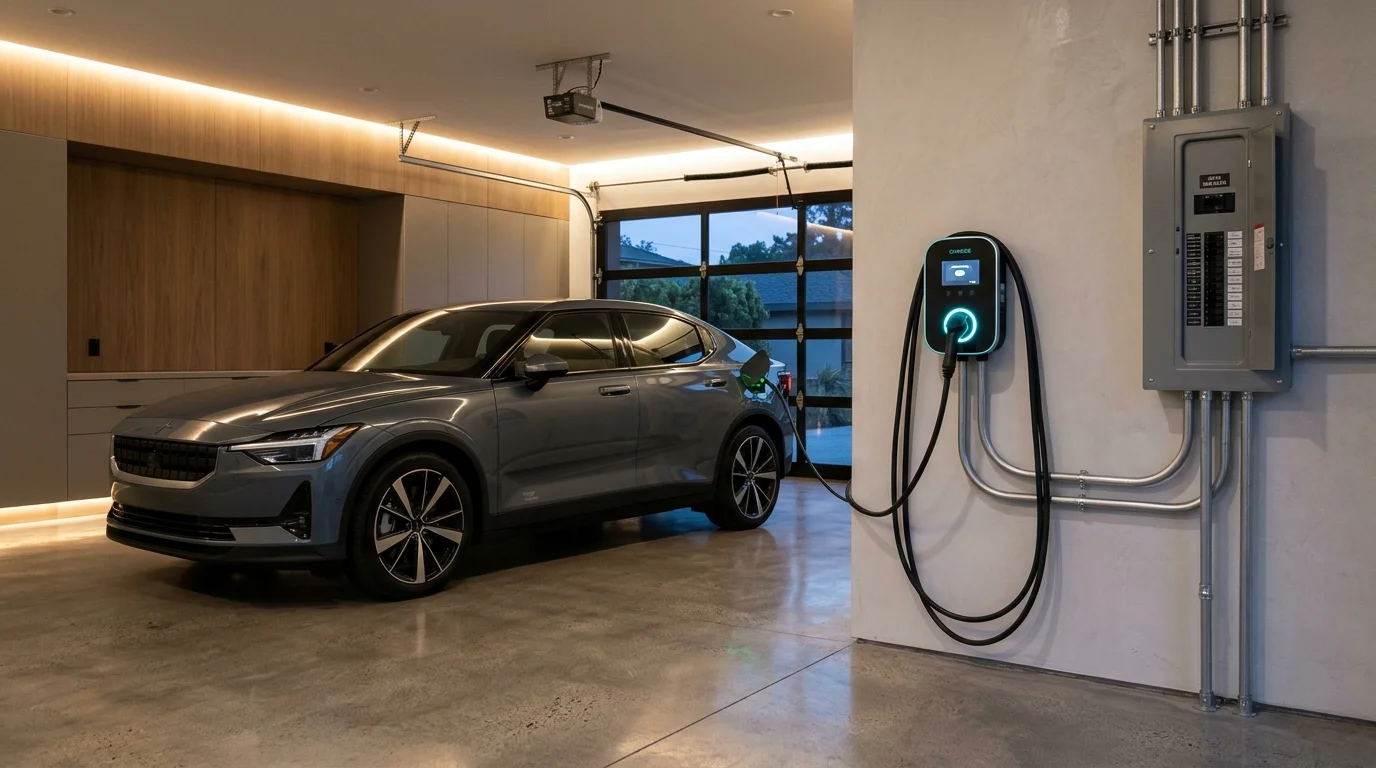
For most electric vehicle (EV) owners worldwide, the primary "fuel station" is not a public commercial hub along the motorway, but their own garage, driveway, or assigned parking bay. Survey data cited in the IEA Global EV Outlook 2026 indicates that EV owners worldwide charge privately (at home or at a workplace) almost 75% of the time, while public fast charging accounts for around 10%. Overnight residential charging represents the cornerstone of electric mobility, allowing drivers to start each day with a replenished battery while avoiding commercial fast-charger premiums and capturing off-peak domestic electricity rates.
However, transitioning to home EV charging introduces critical practical questions for vehicle owners and property managers alike:
- What is the difference between standard domestic sockets, portable charging cables, and hardwired wallbox stations?
- How do you accurately estimate charging time, and why does an 11 kW charger not always deliver 11 kW to your battery?
- How do you calculate the actual electricity cost per recharge and per kilometer driven?
- Can your existing home electrical service panel handle the continuous electrical load of an EV, or will you risk tripping the main breaker?
- How can tenants and apartment residents charge their vehicles when parking in shared multi-unit buildings?
This comprehensive technical guide breaks down residential electric vehicle charging from the perspective of both the car owner and the household electrical system. It covers regional charging classifications (North American Level 1/Level 2 vs. International Single-Phase/Three-Phase AC), equipment terminology, real-world charging physics, electrical safety codes, dynamic load management, and smart solar integration.
1. What Is Home EV Charging and How Does It Work?
To understand residential charging, it is essential to clarify a fundamental engineering concept: electric vehicles store electricity as Direct Current (DC) inside their high-voltage battery packs, but residential power grids deliver Alternating Current (AC).
Commercial ultra-rapid public chargers (such as 150 kW to 350 kW DC fast chargers) house massive industrial rectifiers inside the roadside cabinet. They convert grid AC into high-voltage DC externally and feed it directly into the vehicle's battery.
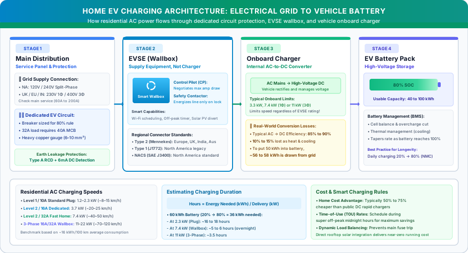
In contrast, virtually all residential charging is Alternating Current (AC) charging (though specialized, low-power residential DC wallboxes exist for niche bidirectional V2H setups or high-end installations). When you plug in at home, the wall unit does not charge the battery directly; instead, it supplies safe, controlled AC electricity to an internal component inside the car known as the Onboard Charger (OBC). The onboard charger rectifies the AC supply into the high-voltage DC required by the battery cells.
EVSE vs. Onboard Charger: The Crucial Equipment Distinction
In everyday conversation, the unit mounted on a garage wall is often called an "EV charger." In electrical engineering and regulatory standards, however, that wall unit is termed Electric Vehicle Supply Equipment (EVSE).
The distinction matters:
- The EVSE (Wallbox or In-Cable Control Box): A specialized electrical control and safety interface. It does not convert AC to DC, nor does it regulate battery charging voltage directly. Its primary role is to manage pilot safety communications, control circuit energization via internal contactors, and provide specified monitoring functions. Depending on its design and applicable standards, the EVSE may monitor protective-earth continuity, pilot signals and specified electrical faults. Its protection functions must be verified from the manufacturer's technical documentation. Crucially, overcurrent and short-circuit protection are provided by the dedicated upstream circuit breaker (MCB / RCBO) in the building's electrical panel.
- The Onboard Charger (OBC): The actual AC-to-DC converter, located physically inside the vehicle's chassis. The power rating of this onboard unit (typically 3.3 kW, 7.4 kW, 11 kW, or rarely 22 kW) sets the absolute physical ceiling on how fast the car can charge from any AC supply.
The Automated Safety Handshake
When you insert an EV charging plug into your vehicle's inlet, the cable pins do not become live with 230V or 240V electricity immediately. Under international standards such as SAE J1772 and IEC 61851-1, a precise low-voltage communication protocol takes place before any main electrical contactors close:
- Physical Latch & Proximity Verification: The Proximity Pilot (PP) pin detects that the plug is fully seated and mechanically locked into the vehicle's charge port, preventing accidental disconnection under load.
- Current Negotiation via Control Pilot: The Control Pilot (CP) line transmits a 1 kHz pulse-width modulated (PWM) signal between the EVSE and the vehicle. The EVSE broadcasts the maximum continuous electrical current the household circuit can safely supply (e.g., 16A or 32A).
- Vehicle Readiness State: The vehicle's central computer assesses battery state, cell temperatures, and onboard charger limits, and signals back that it is ready to receive power.
- Contactor Closure: Only after both sides confirm a safe ground connection and mutual compatibility does the EVSE close its internal electromechanical contactor, energizing the high-power AC conductors.
- Continuous Ground & Fault Monitoring: Depending on the specific EVSE design and manufacturer specifications, the system continuously monitors pilot signals and earth continuity. If an earth fault, loss of ground continuity, or connector latch release is detected, the contactors open to interrupt power and mitigate shock hazards.
2. Understanding Home Charging Equipment (EVSE)
Residential charging equipment is categorized into standardized operational modes and regional power configurations. Understanding these classifications prevents costly compatibility mistakes when purchasing home charging hardware.
Which Home Charger Should You Choose? (Quick Decision Guide)
Before examining detailed technical wiring codes, EV owners can determine their ideal charging setup using three practical daily driving profiles:
- Daily Commute Under 40 km (Light Commuter): A portable Mode 2 / Level 1 charger connected to a dedicated, professionally verified fixed outlet can replenish daily commuting energy overnight. However, charging is slow, and strict adherence to socket safety and local utility rules is mandatory.
- Daily Commute 40 to 100 km (Standard Household Sweet Spot): A dedicated 7.4 kW Level 2 / Mode 3 wallbox (32A @ 230V/240V) represents the ideal balance for most single-family residences. It replenishes a typical daily commute in under 2 hours and provides an overnight 20% to 80% replenishment in 5 to 7 hours without requiring expensive service upgrades.
- High-Mileage Drivers, Dual-EV Homes, or 3-Phase Supplies: If your property has a three-phase electrical supply (common in Europe, Australia, and larger urban homes) and your vehicle supports 11 kW AC charging, an 11 kW three-phase wallbox provides rapid 3 to 5-hour replenishment.
The Four International Charging Modes (IEC 61851-1)
International standards establish four operating modes for electric vehicle charging:
- Mode 1 (Direct Connection without Control Equipment): Direct connection of an electric vehicle to a standard household AC socket-outlet using a standard cable without supplementary control electronics or communication (no control pilot handshake or continuous earth verification). Because standard household circuits lack EV-specific safety interlocks, some jurisdictions prohibit or restrict Mode 1 charging (as highlighted in IEC installation standards and national guidelines such as NITI Aayog's infrastructure handbook), while others permit it only under tightly controlled low-current conditions. Note that using unrated household extension cords is a separate, hazardous practice that should never be confused with standard Mode 1 cabling.
- Mode 2 (In-Cable Control Box / Portable EVSE): A portable EVSE fitted with an In-Cable Control and Protecting Device (IC-CPD) connects to a suitable fixed outlet only where permitted by applicable national regulations. Outlet rating, circuit protection, earthing, manufacturer instructions and local utility requirements must all be verified before use.
- Mode 3 (Dedicated AC Wallbox): A permanently installed wallbox connected to a dedicated AC branch circuit. It provides automated control pilot handshaking, electromechanical contactor isolation, and specialized earth leakage / DC fault monitoring. Crucially, thermal overcurrent and short-circuit protection must be supplied by a dedicated upstream circuit breaker (MCB / RCBO) in the distribution panel, sized specifically to protect the circuit conductors.
- Mode 4 (Direct Current Fast Charging): Off-board DC charging stations (50 kW to 350+ kW). Because of immense power requirements (typically 400V–480V three-phase with 100A+ feeds) and high equipment capex, Mode 4 is virtually exclusive to commercial and highway charging corridors.
Regional Residential Electrical Architectures
A common source of confusion in online EV forums is the mixing of North American charging terms with European, British, and Asian electrical standards:
| Region | Grid Service Type | Nominal Voltage | Typical Residential Circuit Amperage | Maximum AC Power on Single Phase |
|---|---|---|---|---|
| North America (US & Canada) | Split-Phase AC | 120V (Line-Neutral) 240V (Line-Line) |
15A, 20A (120V) 30A, 40A, 50A, 60A (240V) |
Up to 11.5 kW (48A @ 240V hardwired) Rarely up to 19.2 kW (80A) |
| Europe & United Kingdom | Single-Phase & Three-Phase AC | 230V (Single-Phase) 400V (Three-Phase Line-Line) |
16A, 32A (Single-Phase) 16A, 32A (Three-Phase) |
7.4 kW (32A @ 230V Single-Phase) 11 kW to 22 kW on Three-Phase |
| India & South Asia | Single-Phase & Three-Phase AC | 230V (Single-Phase) 415V (Three-Phase Line-Line) |
16A, 32A (Single-Phase) 16A, 32A (Three-Phase) |
Up to 3.7 kW (16A, often 3.3 kW vehicle-limited) to 7.4 kW (32A Single-Phase) 11 kW on Three-Phase |
| Australia & New Zealand | Single-Phase & Three-Phase AC | 230V / 240V Single-Phase 400V / 415V Three-Phase |
16A, 32A (Single-Phase) 16A, 32A (Three-Phase) |
7.4 kW (Single-Phase) 11 kW to 22 kW on Three-Phase |
Connector Standards: Type 1, Type 2, and NACS (SAE J3400)
Depending on where you live and the make of your vehicle, you will encounter one of three predominant residential AC charging connectors:
- Type 1 (SAE J1772): A 5-pin circular connector designed exclusively for single-phase AC electricity. Historically dominant in North America and Japan.
- Type 2 (Mennekes / IEC 62196-2): A 7-pin connector that is widely used as the primary connector for four-wheeler passenger EV AC charging across Europe, the United Kingdom, Australia, and passenger EVs in India. Its versatile pin geometry natively supports both single-phase AC (up to 7.4 kW) and three-phase AC (up to 22 kW) within the same physical inlet. However, drivers should distinguish between widely adopted industry practices and mandatory statutory standards: always verify your vehicle's physical inlet and local regulations, as electric two-wheelers, three-wheelers, and certain imported models rely on different configurations (such as dedicated 15A/16A industrial plugs, Type 1, or light-EV connectors under IS 17017).
- NACS (North American Charging Standard / SAE J3400): Originally developed by Tesla and standardized as SAE J3400, this compact connector combines AC charging and high-power DC fast charging into a single set of primary pins. It has been adopted by nearly all major automakers in the North American market.
3. Level 1, Level 2, and International Residential AC Charging Classifications
Terminology for home charging differs fundamentally between North America and the rest of the world. Rather than treating these classifications as identical, it is important to understand regional frameworks clearly: North American Level 1 and Level 2 charging classifications are based on supply voltage and charging configuration. SAE J1772 defines the associated AC charging coupler and communication requirements for compatible vehicles. In contrast, international standards follow the protocol-based modes of IEC 61851-1:
- North American System (Voltage-Centric):
- Level 1: Operates strictly on standard 120V AC household utility power, supplying 12A continuous current (1.4 kW) on a 15A branch circuit.
- Level 2: Operates on 208V to 240V split-phase AC power, ranging from 16A (3.8 kW) up to 48A (11.5 kW) or rarely 80A (19.2 kW).
- International & Commonwealth Systems (Connection & Voltage Centric):
- In the UK, Europe, India, and Australia, residential utility power is natively 230V single-phase or 400V three-phase.
- A 230V domestic or industrial socket cable with an In-Cable Control Box (ICCB) is classified as Mode 2, delivering approximately 2.3 kW to 2.8 kW (roughly double the power of a North American Level 1 plug). Note that Mode 2 is an equipment communication classification, not a power level equivalent to Level 1.
- A dedicated, hardwired charging station connected to a permanent circuit is classified as Mode 3, delivering 7.4 kW on single-phase (32A @ 230V) or 11 kW to 22 kW on three-phase (16A/32A @ 400V).
| Charging Classification | Operating Voltage & Current | Nominal Continuous Power | Typical Driving Range Added per Hour* | Time to Add 40 kWh (~250 km Range) | Installation & Electrical Requirements |
|---|---|---|---|---|---|
| Level 1 (North America) | 120V AC, 12A continuous (on 15A branch circuit) | 1.3 to 1.4 kW | 6 to 7 km / hour (4 to 5 miles / hour) |
30 to 35 hours | Existing standard NEMA 5-15 wall socket; dedicated circuit strongly recommended. |
| Domestic Socket Mode 2 (UK / EU / IN / AU) | 230V AC, 10A to 15A/16A (national standard dependent) | 2.3 to 3.7 kW (often capped at 3.3 kW by vehicle OBC) | 11 to 16 km / hour (7 to 10 miles / hour) |
Approximately 12 to 20 hours, depending on charging current, vehicle limits and charging efficiency. | Dedicated, manufacturer-approved portable EVSE connected only to a suitable fixed outlet where permitted by local regulations. Socket type, circuit protection, earthing and installation suitability must be verified for the specific country and installation. In India, check the applicable CEA requirements and local DISCOM conditions before relying on domestic-socket charging. |
| Level 2 / 16A Dedicated (Mid-Speed) | 208V–240V (NA) or 230V (Int'l), 16A continuous | 3.3 to 3.8 kW | 16 to 21 km / hour (10 to 13 miles / hour) |
12 to 14 hours | Dedicated breaker (sized per local code), wiring as calculated by a qualified electrician, approved receptacle or wallbox. |
| Level 2 / 32A Standard Home Wallbox | 240V (NA) or 230V (Int'l), 32A continuous | 7.0 to 7.7 kW | 36 to 41 km / hour (22 to 26 miles / hour) |
5.8 to 6.5 hours (Complete overnight replenishment) |
Dedicated breaker (sized per local code), copper wiring as calculated by a qualified electrician (typically 6.0–10.0 mm²), Type A RCD + 6mA DC protection. |
| Level 2 / 48A High-Power (North America) | 240V AC, 48A continuous | 11.5 kW | 57 to 64 km / hour (35 to 40 miles / hour) |
3.8 to 4.2 hours | Dedicated breaker (sized per local code), wiring as calculated by a qualified electrician. Installation method and permitted connection type must be verified against applicable electrical codes and EVSE listing (hardwiring is standard practice for higher-current residential EVSE). |
| Three-Phase 16A Wallbox (Europe / AU) | 400V 3-Phase AC, 16A per phase | 11.0 kW | 54 to 61 km / hour (34 to 38 miles / hour) |
4.0 to 4.4 hours | 3-phase domestic service, dedicated 4-pole MCB (sized per local code), 5-core wiring as calculated by a qualified electrician; vehicle must have 11 kW 3Φ OBC. |
| Three-Phase 32A Wallbox (Europe / Commercial) | 400V 3-Phase AC, 32A per phase | 22.0 kW | 110 to 124 km / hour (68 to 77 miles / hour) |
~2.0 hours | Heavy 3-phase grid supply (rare in small homes), dedicated 4-pole MCB (sized per local code), cabling as calculated by a qualified electrician; few passenger EVs support 22 kW AC. |
*Note on charging speeds and durations: All charging durations and driving ranges in this table are approximate engineering estimates. They assume a typical passenger EV efficiency of 16 to 18 kWh per 100 kilometers (3.5 to 4.0 miles per kWh) and an AC-to-DC conversion efficiency of 88% (and ~82% on low-power Level 1). Actual replenishment times vary based on battery temperature, vehicle onboard charger limits, and real-world grid voltage.
Is a Standard Wall Socket or Portable Charger Really Enough?
Many first-time EV buyers ask whether installing a dedicated wallbox is strictly necessary. The honest answer depends on your daily commuting distance and rigorous electrical safety compliance:
- When Portable / Domestic Socket Charging is Sufficient: If your daily round-trip commute is under 40 to 60 kilometers (25 to 40 miles), plugging into a suitable, verified socket for 10 to 12 hours overnight will easily replenish the energy used each day. Drivers with short urban commutes or plug-in hybrid electric vehicles (PHEVs with smaller 10–18 kWh batteries) frequently manage using portable chargers.
- When a Dedicated 7.4 kW Wallbox is Recommended: If your daily commute regularly exceeds 75 kilometers, if you take frequent long trips, or if multiple EVs share a household connection, slow socket charging may struggle to keep up with daily energy consumption. A 7.4 kW or 11 kW wallbox provides substantial replenishment from 20% to 80% overnight in 5 to 8 hours, giving drivers peace of mind and flexibility.
Plugging an electric vehicle into a domestic wall socket requires extreme technical caution. Never assume that an existing 16A wall socket in an Indian home is safe for EV charging simply because the plug fits. In standard residential electrical installations, 16A power sockets are frequently daisy-chained with other high-power appliances, wired with aging conductors, or connected to unverified earthing paths.
From a regulatory standpoint, India's Central Electricity Authority (Measures relating to Safety and Electric Supply) Regulations (Regulation 124) explicitly prohibit the use of portable socket-outlets, extension sets, and second supply leads for EV charging to eliminate hazardous temporary wiring. However, this clause should not be misconstrued as an automatic ban on every fixed wall socket, nor does it mean that any standard 16A socket is universally compliant or safe.
The use of a fixed domestic socket for Mode 2 charging should not be assumed to be automatically permitted or safe. Owners must verify the applicable CEA requirements, local DISCOM conditions, vehicle manufacturer's instructions and the suitability of the complete electrical installation before using this method. Specifically, vehicle owners must ensure that:
- Vehicle Manufacturer Authorization: The EV automaker explicitly approves Mode 2 residential charging with the supplied portable cable.
- Dedicated Fixed Outlet: Where fixed-outlet Mode 2 charging is permitted, the outlet must be suitable for the EVSE's rated current and installed on an appropriately designed, independently protected circuit. Its compliance and suitability must be confirmed by a qualified electrician under applicable Indian requirements.
- Verified Earthing & Conductor Gauge: Continuous copper wiring of adequate cross-section must be confirmed, along with verified low earth loop resistance.
- DISCOM & Sanctioned Load Compliance: Total demand during charging must remain strictly within the consumer's contracted sanctioned load to avoid utility penalties.
Because safety enforcement and local interpretations vary by distribution utility, consulting a licensed electrical inspector and adhering to local DISCOM guidelines is strongly recommended. For regular passenger EV charging, a dedicated hardwired Mode 3 wallbox remains the safest, most durable solution.
4. How to Estimate EV Charging Time (Formulas & Real-World Variables)
Estimating how long an EV takes to charge at home requires understanding four interdependent electrical and thermal variables:
Where:
- Δ Energy Needed (kWh): Usable Battery Capacity (kWh) × [(Target SoC % − Starting SoC %) ÷ 100]
- Effective AC Power (kW): The lesser of the EVSE supply power or the vehicle's internal onboard charger limit.
- Conversion Efficiency (η): The efficiency of the vehicle's onboard AC-to-DC rectifier, cooling pumps, and computer standby consumption (empirically 0.85 to 0.90).
Variable 1: The Onboard Charger Bottleneck
A common beginner frustration occurs when a driver installs an expensive 11 kW or 22 kW home wallbox, only to find their vehicle charges at only 7.4 kW.
Remember: the vehicle's onboard charger (OBC) always dictates the maximum AC charging rate.
- Single-Phase EV on Three-Phase EVSE: If you connect an electric car with a 7.4 kW single-phase onboard charger (common on many passenger EVs) to a 22 kW three-phase wallbox, the vehicle can only draw from one phase at 32A, capping charging speed at 7.4 kW.
- Three-Phase EV on Single-Phase EVSE: If an EV equipped with an 11 kW three-phase onboard charger is connected to a standard single-phase residential supply, charging speed depends on whether the vehicle's OBC can accept a full 32A on a single phase (delivering 7.4 kW) or is limited to 16A per module (delivering only 3.7 kW). Always verify your specific vehicle's single-phase AC charging rating in the owner's handbook before selecting home charging equipment.
Variable 2: Real-World Conversion Losses (The 10% to 15% Factor)
Charging a battery is not 100% efficient. When grid AC power enters the car, several components consume energy:
- Rectification Losses: Semiconductor diodes and transistors in the onboard charger convert AC to DC with 2% to 6% heat generation.
- Thermal Management Overhead: The vehicle's high-voltage Battery Management System (BMS) actively operates coolant circulating pumps, radiator fans, and internal chillers/heaters to keep battery cells within their optimal chemical window (typically 20°C to 35°C).
- Electronic Standby Consumption: Depending on vehicle make and firmware, vehicle ECUs, telematics, and sensors remain active during charging, typically drawing an illustrative 100 to 300 Watts of baseline power.
Because of these losses, delivering 50 kWh of net energy into an EV battery typically requires drawing approximately 55 to 58 kWh from the residential electrical meter under normal operating temperatures.
Counter-intuitively, charging at very low power (such as 1.3 kW on Level 1) is often less energy-efficient in real-world testing (with illustrative field measurements often yielding 75% to 85% net efficiency) than charging at 7.4 kW (where efficiency typically reaches 88% to 92% under moderate temperatures). Because the vehicle's computer systems, telematics, and coolant pumps draw a constant parasitic standby baseline (e.g. an illustrative ~150W to 250W) for the entire multi-hour duration, that overhead represents nearly 15% to 20% of a 1.3 kW feed, but less than 3.5% of a 7.4 kW Level 2 wallbox. Note that exact efficiencies vary by vehicle model, onboard charger design, and ambient thermal conditions.
Worked Calculation Examples
Scenario A: Typical Mid-Size Commuter EV (e.g., MG4, Hyundai Kona, or BYD Atto 3)
- Battery Specification: 64 kWh usable capacity, single-phase 7.4 kW onboard charger.
- Charging Session: Arriving home at 20% SoC and replenishing to 80% SoC (ΔSoC = 60%).
- Net Energy Needed: 64 kWh × 0.60 = 38.4 kWh.
- Energy Drawn from Grid (at 88% efficiency): 38.4 kWh ÷ 0.88 = 43.6 kWh.
- Charging Time on 2.3 kW Portable Plug (10A @ 230V):Time = 38.4 kWh ÷ (2.3 kW × 0.85) ≈ 19.6 hours
- Charging Time on 7.4 kW Dedicated Wallbox (32A @ 230V):Time = 38.4 kWh ÷ (7.4 kW × 0.89) ≈ 5.8 hours
Scenario B: Long-Range Premium Crossover (e.g., Tesla Model Y Long Range or Kia EV6)
- Battery Specification: 77 kWh usable capacity, 11 kW three-phase onboard charger.
- Charging Session: Depleted to 10% SoC, charging to 80% SoC (ΔSoC = 70%).
- Net Energy Needed: 77 kWh × 0.70 = 53.9 kWh.
- Charging Time on Standard 7.4 kW Single-Phase Wallbox (assuming OBC supports 32A single-phase parallel charging):Time = 53.9 kWh ÷ (7.4 kW × 0.89) ≈ 8.2 hours*(Note: If the vehicle's 11 kW three-phase OBC lacks internal module paralleling and draws only 16A / 3.7 kW on a single-phase supply, charging duration extends to approximately 16.3 hours).*
- Charging Time on 11 kW Three-Phase Wallbox:Time = 53.9 kWh ÷ (11.0 kW × 0.90) ≈ 5.4 hours
5. How Much Does It Cost to Charge an EV at Home? (Calculations & Running Costs)
Calculating home charging cost involves two straightforward steps: determining total grid electricity consumed (including efficiency losses) and multiplying by your utility tariff.
To explore appliance electricity mathematics and tariff structures in greater depth, review our tutorials on How to Calculate Home Electricity Consumption in kWh and How to Read an Electricity Bill: Units, Fixed Charges and Taxes.
Illustrative Global Cost Comparison: EV Home Charging vs. Petrol / Diesel (Hypothetical Benchmark)
To demonstrate comparative operational economics, the following worked model assumes an illustrative driving pattern of 1,200 kilometers (750 miles) per month, with an EV consuming 17 kWh per 100 km (including charging conversion losses):
- Total monthly charging energy drawn from grid: 12 × 17 kWh = 204 kWh.
- Equivalent internal combustion engine (ICE) car fuel consumption: 7.5 Liters per 100 km (31.3 MPG) = 90 Liters (23.8 US gallons) of petrol monthly.
| Market & Tariff Benchmark | Representative Illustrative Tariff (Benchmark Reference) | Monthly EV Home Charging Cost (204 kWh) | Monthly Petrol / Gasoline Fuel Cost (90 Liters) | Monthly Operational Fuel Savings |
|---|---|---|---|---|
| United States (Standard Flat Rate) | $0.165 per kWh (US EIA Residential Average Benchmark) | $33.66 | $81.00 ($3.40 / gallon) | $47.34 / month (~58% cheaper) |
| United States (Off-Peak EV TOU Rate) | $0.080 per kWh (e.g. Utility EV Time-of-Use Off-Peak Scenario) | $16.32 | $81.00 ($3.40 / gallon) | $64.68 / month (~80% cheaper) |
| United Kingdom (Standard Variable Tariff) | £0.245 per kWh (Ofgem Default Price Cap Benchmark) | £49.98 | £130.50 (£1.45 / liter) | £80.52 / month (~62% cheaper) |
| United Kingdom (Overnight EV Tariff) | £0.075 per kWh (e.g. Dedicated EV Overnight Window Benchmark) | £15.30 | £130.50 (£1.45 / liter) | £115.20 / month (~88% cheaper) |
| India (Higher-Tier Domestic Slab) | ₹8.00 per kWh (Illustrative Urban Progressive Slab Assumption) | ₹1,632 | ₹8,640 (₹96 / liter petrol) | ₹7,008 / month (~81% cheaper) |
*Important Methodological Scope & Cost Disclaimer: All tariff figures in this table are illustrative analytical assumptions based on representative regional benchmarks (synthesized from US Energy Information Administration residential averages, UK Ofgem price cap benchmarks, and representative Indian metropolitan utility domestic slabs). Because utility rate schedules, local fuel costs, fuel taxes, and seasonal surcharges vary widely by state, region, and distribution company, readers should treat these as analytical scenarios rather than universal figures and calculate actual savings using their own local utility billing rates. Furthermore, this comparison evaluates marginal electricity and fuel consumption expenses only; it does not incorporate capital outlays (vehicle price premium, wallbox EVSE hardware, electrical wiring and panel upgrade costs), recurring monthly fixed/demand charges on utility bills, battery depreciation, annual motor insurance, or vehicle maintenance.
Practical Case Study: EV Home Charging in India (Illustrative Benchmark)
To understand how home charging economics work for Indian urban drivers, consider an illustrative electric SUV with an approximately 40.5 kWh usable battery capacity. Actual usable capacity, energy efficiency and real-world range vary by vehicle model, variant and model year:
- Routine Commuter Session (20% to 80% State of Charge):
- Net battery energy replenishment: 40.5 kWh × 0.60 = 24.3 kWh.
- Electricity drawn from grid meter (at 88% AC onboard charger efficiency): 24.3 kWh ÷ 0.88 ≈ 27.6 kWh (units).
- Cost at illustrative domestic rate of ₹8.00 per unit: 27.6 units × ₹8.00 = ₹220.80.
- Real-world driving range added: ~160 to 180 km (assuming typical urban consumption of 13.5 to 15.0 kWh per 100 km).
- Effective Fuel Cost per Kilometer: Approximately ₹1.25 to ₹1.38 / km, compared to ₹6.50 to ₹8.50 / km for an equivalent petrol automatic compact SUV in Indian city traffic (yielding over 75% operational fuel savings).
India Ministry of Power 2024 Regulatory Provisions
Under the Government of India Ministry of Power's revised Guidelines and Standards for EV Charging Infrastructure (2024), residential consumers operate under clearly defined regulatory provisions:
- Existing Domestic Connection Permitted: Residents are legally entitled to charge their electric vehicles using their existing domestic electrical connection, and standard domestic electricity tariffs apply.
- Dedicated EV Meter Option: Consumers may optionally apply to their local power distribution utility (DISCOM) for a separate, metered EV connection and dedicated EV tariff, where authorized by the respective State Electricity Regulatory Commission (SERC).
- Mandatory Load Enhancement When Exceeding Sanctioned Load: If adding an EV charger causes aggregate household demand to exceed the home's currently contracted or sanctioned load, the consumer must formally apply to the DISCOM to enhance their sanctioned load, avoiding unauthorized overdraw penalties.
- Economic Viability of a Separate EV Meter: A dedicated EV meter is an option whose financial benefit depends entirely on local state tariff structures. In some states, dedicated EV meters carry separate monthly fixed demand charges; consumers should evaluate whether avoiding higher domestic consumption slabs outweighs the fixed meter charges before applying.
For a broader methodology on calculating appliance running costs, see our detailed guide on How to Calculate the Electricity Cost of Any Appliance.
6. Electrical Requirements Before Installing a Home Charger
An electric vehicle charger is fundamentally different from any other appliance in your home. While an oven, air conditioner, or water heater cycles on and off intermittently via a thermostat, an EV charger draws maximum continuous rated amperage for 4 to 8 consecutive hours.
This continuous thermal load places unique stress on conductors, breakers, and distribution panels. Before purchasing a wallbox, a certified electrician must verify five vital electrical requirements:
1. Assessing Household Service Capacity (Load Calculation)
Residential electrical supplies have an aggregate maximum capacity:
- North America: Typically 100A, 150A, or 200A main service panel at 240V split-phase.
- United Kingdom & Europe: Typically 60A, 80A, or 100A main service cut-out fuse on 230V single-phase.
- India: Contracted or sanctioned load, typically measured in kilowatts (5 kW to 10 kW for apartments and urban homes).
If your home already operates multiple heavy electrical loads—such as central air conditioning, an electric heat pump, an induction range, and an electric instantaneous water heater—adding a 32A (7.4 kW) continuous EV load can push the household peak demand past the main service fuse rating during dinner hours.
To learn how to calculate your home's total connected electrical load and ensure adequate capacity headroom, consult our in-depth reference on Home Electrical Load Calculation: Connected Load, Circuit Sizing and MCB Basics.
2. Sizing Continuous Dedicated Circuits: Regional Electrical Codes
Because EV charging draws high current for hours, electrical codes specify dedicated circuit sizing differently across jurisdictions:
United States Standards (NEC Article 625 — Illustrative Examples Only)
Under the National Electrical Code (NEC), particularly Article 625, in the United States:
- An EV charging circuit is classified as a continuous load (a load sustained for 3 hours or more).
- Branch circuit overcurrent protective devices (breakers) and conductors must be sized at 125% of the continuous charging current (or conversely, the continuous EV load must not exceed 80% of the breaker rating).
(Note for Canada: Canada follows the Canadian Electrical Code (CEC) and applicable provincial safety regulations. Do not apply US NEC sizing rules directly to Canadian installations without verifying local CEC compliance).
| Continuous Charging Current | Illustrative Breaker Rating (Subject to 125% Rule & Sizing Calculation) | Continuous Power (@ 240V) | Indicative Conductor Sizing (As calculated by a qualified electrician)* |
|---|---|---|---|
| 16 Amperes | 20A Breaker (Example baseline) | 3.8 kW | As calculated by a qualified electrician (typically 12 AWG Copper for standard short runs) |
| 24 Amperes | 30A Breaker (Example baseline) | 5.8 kW | As calculated by a qualified electrician (typically 10 AWG Copper for standard short runs) |
| 32 Amperes | 40A Breaker (Example baseline) | 7.7 kW | As calculated by a qualified electrician (typically 8 AWG Copper for standard short runs) |
| 40 Amperes | 50A Breaker (Example baseline) | 9.6 kW | As calculated by a qualified electrician (typically 6 AWG Copper for standard short runs) |
| 48 Amperes | 60A Breaker (Example baseline) | 11.5 kW | As calculated by a qualified electrician (typically 6 AWG (90°C) or 4 AWG Copper; installation method and permitted connection type must be verified against applicable electrical codes and EVSE listing; hardwired installation is standard practice for higher-current residential EVSE systems. Note that terminal temperature ratings under NEC 110.14(C), typically 75°C, dictate conductor ampacity selection.) |
International & Indian Standards (IEC 60364-7-722, BS 7671 & IS 732 — Illustrative Examples Only)
Outside the United States, EV circuit sizing must follow the applicable national wiring rules and local installation requirements. For example, IEC-based installations use design-current, protective-device and conductor-capacity coordination (Ib ≤ In ≤ Iz), while BS 7671 includes specific requirements for EV charging circuits in the United Kingdom. Do not assume that one breaker rating, cable size or diversity factor applies across all countries. The applicable design current and any permitted diversity assumptions must be determined under the relevant national wiring rules and installation conditions.
| Continuous Charging Current | Indicative Dedicated MCB Rating (Subject to calculation) | Continuous AC Power | Indicative Conductor Sizing (As calculated by a qualified electrician)* |
|---|---|---|---|
| 16 Amperes (1-Phase / 3-Phase) | 16A or 20A MCB (Subject to load and coordination calculation) | 3.7 kW (230V 1Φ) / 11.0 kW (400V 3Φ) | As calculated by a qualified electrician (typically 2.5 mm² to 4.0 mm² depending on run length and installation method) |
| 32 Amperes (1-Phase / 3-Phase) | 32A or 40A MCB (Subject to load and coordination calculation) | 7.4 kW (230V 1Φ) / 22.0 kW (400V 3Φ) | As calculated by a qualified electrician (typically 6.0 mm² to 10.0 mm² depending on run length, grouping, and voltage drop limits) |
*Important Engineering Disclaimer on Cable and MCB Sizing: The circuit breaker ratings and conductor sizes listed in the tables above are illustrative design benchmarks for typical short indoor runs, not universal specifications. Never treat these as one-size-fits-all figures. The final cable cross-section, conductor metal (copper vs aluminium), insulation temperature rating, and breaker tripping characteristics (Type B vs Type C curve) must be calculated individually by a certified electrician in accordance with local electrical safety codes, accounting for circuit length, installation method (conduit, surface clipped, underground ducting), ambient operating temperatures, grouping derating, and strict compliance with maximum permissible voltage drop (under 3% at continuous full load).
To see how these electrical principles apply in practice, consider a homeowner installing a standard 32A (7.4 kW) wallbox in an attached garage with a 15-meter cable run from the main distribution panel:
- Upstream Capacity Check: The electrician audits the household service (e.g. 60A or 100A main service cut-out) and existing peak household loads to confirm sufficient continuous capacity headroom.
- Dedicated Circuit & MCB: The circuit connects to an independent, dedicated protective device, with circuit design current and any permitted diversity assumptions determined under applicable local regulations.
- Conductor Sizing & Voltage Drop: Rather than using minimum-gauge cable, the electrician specifies 6 mm² (or 10 mm² for longer runs) multi-core copper cable to keep continuous full-load voltage drop comfortably below 3%, preventing cable overheating and onboard charger low-voltage dropouts.
- Ground-Fault & DC Leakage Safety: The installation includes a Type A RCD at the distribution panel paired with the wallbox's integrated IEC 62955-compliant 6 mA RDC-DD (or an external Type B RCD where required by local code).
- Earthing Verification: On UK PME systems, an approved Open-PEN disconnection device or an independent TT earth rod is verified; in India, earth resistance and neutral integrity are tested per CEA norms.
Important Safety Notice: This walkthrough and all sizing tables in this guide are provided strictly for educational and analytical purposes. Home EV charging is not a DIY electrical project. All branch circuit design, panel modifications, conduit installation, and commissioning must be executed exclusively by a licensed, certified electrician in compliance with local statutory codes and utility requirements.
3. Residual Current & Earth Leakage Protection (The DC Leakage Hazard)
Standard household Residual Current Devices (RCDs) and Ground Fault Circuit Interrupters (GFCIs)—classified as Type AC or standard Type A—are designed to detect alternating current (AC) ground faults.
However, electric vehicle battery systems operate on high-voltage DC. If a semiconductor failure occurs inside the vehicle's onboard charger, a smooth direct-current (DC) residual leakage can travel back through the charging cable. This DC leakage current saturates the magnetic toroidal core of standard household Type A RCDs, effectively "blinding" or paralyzing them so they fail to trip even during a lethal AC shock elsewhere on the property.
Safety standards address this risk according to regional regulatory frameworks:
- International & UK Rules (IEC 60364-7-722 / BS 7671 / IET Guidance): Mandate that every dedicated residential EV chargepoint must be protected against DC fault currents. In accordance with IEC 60364-7-722 and IET technical guidance, this requires either:
- A Type B RCD (which detects AC, high-frequency, and pure smooth DC faults up to several hundred milliamperes), OR
- A Type A RCD combined with a Residual Direct Current Detecting Device (RDC-DD compliant with IEC 62955) that disconnects power if a smooth DC fault exceeding 6 mA is detected. Most modern European wallboxes incorporate this 6 mA DC sensor internally.
- North American Standards (UL 2231-1 & UL 2231-2): In the United States and Canada, EVSE ground-fault protection must comply with the applicable product certification and electrical code requirements. Listed Level 2 equipment commonly incorporates personnel-protection devices such as CCID protection (typically CCID20 with a 20 mA personnel protection trip threshold or CCID5 with 5 mA). The exact protection arrangement must be verified from the EVSE certification and manufacturer's installation instructions.
4. Earthing and Open-PEN Fault Protection (PME / TN-C-S Grids)
A specialized shock hazard exists specifically in jurisdictions utilizing Protective Multiple Earthing (PME or TN-C-S earthing arrangements), which are widespread across the United Kingdom, Ireland, and parts of Commonwealth grids. In a PME system, the electricity distributor combines the incoming neutral conductor and protective earth into a single PEN wire up to the consumer's cut-out.
If an accidental physical break occurs in this supply neutral wire in the street, an Open-PEN fault can cause dangerous voltage differences between exposed conductive parts and the surrounding ground, creating a potentially fatal electric-shock risk.
Under BS 7671 (IET Wiring Regulations Section 722), EV chargepoints connected to PME supplies must implement one of three compliant safeguards:
- Installation of an independent earth electrode (ground rod) to convert the charging point into an isolated TT earthing system;
- An integrated Open-PEN detection device inside the wallbox that automatically disconnects Line, Neutral, and Earth if dangerous supply voltage deviations or neutral-to-earth potential differences are detected in accordance with device specifications and BS 7671 requirements;
- An approved neutral-to-earth potential monitoring system.
Note for other earthing systems: In installations connected to true TT earthing (where the building uses an independent earth rod) or TN-S earthing (where separate neutral and protective earth conductors run continuously back to the substation), Open-PEN neutral potential inversion cannot occur, and separate Open-PEN protective relays are not required.
7. EV Charging in Apartments, Rented Homes, and Shared Parking
While homeowners with private garages enjoy straightforward charging installation, residents of Multi-Unit Dwellings (MUDs), condominiums, and rental properties face institutional hurdles. According to the IEA Global EV Outlook 2026, closing the charging access gap between detached single-family homes and multi-unit housing is the single most critical urban EV infrastructure challenge of this decade.
Common Apartment Metering Architectures
When installing EV charging in a communal residential garage, three primary electrical connection methods exist:
- Direct Connection to the Apartment's Individual Meter:
- How it works: A dedicated armored cable runs from the tenant's individual basement electricity meter up to their deeded parking stall.
- Advantages: Electricity is billed directly on the tenant's existing home electricity bill at standard residential tariffs.
- Challenges: Impractical if the apartment meter room is dozens of floors above the basement parking, or if cable tray routes are congested.
- Connection to Common Building House Services (with Sub-Metering):
- How it works: The wallbox taps into the building's common services distribution board (which powers hallway lighting, elevators, and water pumps). A certified digital sub-meter or smart cloud-connected wallbox tracks kilowatt-hours consumed.
- Advantages: Short cable runs within the parking structure.
- Challenges: Requires formal Homeowners Association (HOA) or resident welfare association (RWA) approval, administrative billing reconciliations, and capacity sharing.
- Dedicated Commercial Community Charging Hub:
- How it works: A specialized EV charging operator (CPO) installs multi-bay charging stations connected to a dedicated high-capacity utility connection. Residents authenticate sessions via RFID cards or mobile apps.
- Advantages: Zero administrative burden on the building management; scalable infrastructure.
- Challenges: The charging operator adds a transaction fee or service margin, resulting in higher electricity costs per kWh than direct domestic tariffs.
"Right to Charge" Legislation and Practical Advice for Apartment Dwellers
Recognizing that HOA boards, housing societies, and landlords historically stalled EV charger requests due to unfamiliarity, governments worldwide are establishing statutory frameworks:
- United States: Comprehensive state legislative databases maintained by the National Conference of State Legislatures (NCSL)—tracking statutes such as California Civil Code § 4745, Florida Statute § 718.113, New York Real Property Law § 339-ll, Colorado SB 13-126, and Washington RCW 64.38.060—demonstrate growing "Right to Charge" protections. These statutes prohibit HOAs and condominium associations from unreasonably denying a resident permission to install an EV charger in their deeded or designated parking space, provided the resident covers installation, insurance, and electricity expenses. Note that specific legal provisions, procedural requirements, owner vs. tenant eligibility, and architectural exemptions vary significantly by state statute; residents should consult their specific state code and association covenants.
- European Union: Under Article 14 of the recast Energy Performance of Buildings Directive (EU) 2024/1275, qualifying new residential buildings and residential buildings undergoing major renovation with more than three car parking spaces must provide pre-cabling for at least 50% of parking spaces and ducting for the remainder. New residential buildings covered by the provision must also include at least one recharging point. National implementation requirements may vary.
- India (Ministry of Power Framework & RWA Coordination): Under the Government of India's revised Ministry of Power EV Charging Infrastructure Guidelines (2024), lawful owners or residents with designated parking spaces in group housing societies are expressly permitted to set up private charging points. The guidelines define two clear electrical pathways:
- Connection to Existing Domestic Meter or Sub-Meter: Residents may connect their private charging point directly to their existing domestic meter (or through a calibrated sub-meter from the building's domestic supply) at standard residential rates, provided household sanctioned load is adequate.
- Separate Dedicated DISCOM Connection: Where pulling private cables from an individual apartment meter is physically impractical, residents and housing societies can apply to the local DISCOM for a separate dedicated metered connection at the parking level under state EV tariff schedules.
- RWA & Society Coordination: The resident submits a proposal to the Resident Welfare Association (RWA) or Apartment Owners Association (AOA) confirming private funding of equipment, dedicated cabling, and safety compliance. If aggregate demand exceeds the building transformer or flat sanctioned load, a formal load enhancement application must be lodged with the DISCOM.
8. Smart Charging, Load Management, and Solar Integration
As electric vehicle adoption surges, running multiple high-amperage chargers simultaneously could strain neighborhood distribution transformers. In response, modern charging hardware is transitioning from "dumb" on/off switches to intelligent, grid-interactive systems.
Dynamic Load Management (DLM): Managing Main Service Capacity
The traditional barrier to installing a 7.4 kW or 11 kW wallbox in an older home is the fear that it will overload the main service cut-out fuse. Upgrading a domestic utility service from 60A to 100A or from 100A to 200A often costs thousands of dollars in utility fees and panel work.
Dynamic Load Management (DLM) can reduce the risk of household service overload and may avoid or defer an electrical service upgrade in installations where the system is compatible and correctly configured:
- A small clamp-on Current Transformer (CT clamp) or digital energy meter is installed at the home's main service entrance, measuring total instantaneous household power consumption in real time.
- The CT sensor communicates with the EVSE via hardwired Modbus cable or encrypted local Wi-Fi.
- If the home's main service fuse is rated for 60A, and household appliances (electric shower, air conditioner, oven) are currently drawing 45A, the smart wallbox automatically throttles the EV charge rate down to 15A.
- As soon as the oven or shower turns off and domestic draw falls to 10A, the wallbox immediately ramps the vehicle back up to its full 32A charging speed.
By dynamically modulating charging current based on real-time household headroom, DLM can substantially reduce the risk of service overload. However, even with DLM installed, property owners must still respect their contracted sanctioned load, local utility connection regulations, and the physical current-carrying capacity of their upstream distribution equipment.
Solar PV Integration: Driving on Pure Sunshine
For households with rooftop solar arrays, smart EV charging represents the ultimate synergy. Rather than exporting surplus midday solar generation to the electrical grid at low feed-in tariffs (often just 3¢ to 8¢ per kWh), smart solar-diverting wallboxes (such as Zappi, Wallbox Pulsar, or Emporia) maximize on-site self-consumption:
- Solar Eco Mode: The wallbox blends grid electricity with solar surplus, maintaining a minimum baseline charging speed while ramping up power whenever rooftop solar generation exceeds household base loads.
- Solar-Surplus Only Mode: The wallbox continuously monitors net solar export and initiates charging only when surplus generation satisfies the vehicle's turn-on threshold. On standard single-phase 230V installations, this typically corresponds to approximately 1.4 kW (the standard 6A minimum pilot communication threshold under IEC 61851-1). However, this turn-on threshold is not a universal constant for all electric cars:
- Certain EV onboard chargers require higher minimum currents (such as 8A or 10A, representing 1.8 kW to 2.3 kW) before commencing a session.
- On three-phase wallbox installations, delivering a minimum 6A across all three phases requires at least 4.1 kW of continuous solar export (unless the wallbox incorporates automatic dynamic phase-switching from 3-phase to 1-phase during low solar hours).
- If passing clouds cause solar generation to fall below the vehicle's minimum operating threshold, smart chargers pause the session until export stabilizes, preventing repeated on/off cycling that can trigger onboard charger fault timeouts.
Driving an EV powered primarily by surplus residential rooftop solar substantially reduces grid electricity purchases and operational emissions, though grid backup remains essential during cloudy intervals, and hardware manufacturing lifecycle emissions must still be recognized.
Bidirectional Charging: V2H (Vehicle-to-Home) Readiness
The cutting edge of residential energy storage is Vehicle-to-Home (V2H) and Vehicle-to-Grid (V2G) bidirectional charging, governed by standards such as ISO 15118-20.
An electric car battery (typically 60 kWh to 100 kWh) contains a substantial volume of electrical energy compared to stationary home batteries (typically 5 kWh to 15 kWh). As an illustrative benchmark, assuming an energy-efficient household consuming 10 to 15 kWh per day, a fully charged 77 kWh battery could theoretically sustain critical household loads for 3 to 5 days. However, real-world backup duration depends directly on actual daily household power draw, usable battery capacity, bidirectional inverter continuous and peak power ratings, and the driver's designated reserve threshold (e.g. keeping 20% SoC for emergency travel).
9. Home EV Charging Safety and Installation Checklist
Installing a high-power electrical appliance requires professional discipline. Use the following structured checklist when planning and commissioning your residential EV charging installation:
Phase 1: Pre-Purchase Electrical Audit
- Inspect the main service panel rating (60A, 100A, or 200A) and verify spare physical breaker slots.
- Calculate existing peak household electrical load to determine available continuous amperage headroom.
- Verify that the incoming earthing system (TN-C-S / PME, TN-S, or TT) complies with local regulations.
- Determine the cable run distance between the main panel and the desired vehicle parking position.
Phase 2: Hardware & Circuit Specification
- Select a dedicated circuit breaker sized specifically for the EV continuous load under local codes (e.g., a 40A MCB as an illustrative baseline for a 32A wallbox under the NEC 125% continuous duty rule, or matching IEC thermal coordination).
- Have the electrician calculate exact copper conductor cross-section based on circuit run distance, installation method, and thermal derating (such as 6 mm² to 10 mm² for typical residential 32A runs) to maintain voltage drop strictly under 3%.
- Ensure the installation incorporates Type A RCD protection paired with internal 6 mA DC fault detection (or external Type B RCD, or UL 2231 CCID in North America).
- If installing in the UK or on PME grids, verify that the wallbox features built-in Open-PEN disconnection or install an independent earth rod.
Phase 3: Physical Placement & Commissioning
- Mount the wallbox at an ergonomic height (typically 1.2 to 1.5 meters from ground level).
- Select an enclosure with an appropriate environmental ingress rating for your mounting location: IP54 or IP65 is recommended for outdoor weather-exposed walls (or NEMA 3R / NEMA 4 in North America), whereas sheltered indoor garages can follow manufacturer placement specifications.
- Verify that the charging cable reaches the vehicle's charge port naturally without taut stretching across walking paths (preventing mechanical strain on the vehicle inlet).
- Electrician must perform post-installation loop impedance tests, RCD trip timing verification, and continuity testing before signing the compliance certificate.
10. Frequently Asked Questions (FAQs)
1. Can I safely charge my electric car from a standard household 3-pin wall socket?
No, you should never assume an existing household wall socket is safe for EV charging without qualified professional inspection. In India, under the Central Electricity Authority (Measures relating to Safety and Electric Supply) Regulations (Regulation 124), the use of portable socket-outlets, extension cords, and second supply leads for EV charging is explicitly prohibited.
The use of a fixed domestic socket for Mode 2 charging should not be assumed to be automatically permitted or safe. Owners must verify the applicable CEA requirements, local DISCOM conditions, vehicle manufacturer's instructions and the suitability of the complete electrical installation before using this method. Crucially:
- Manufacturer Authorization: The EV manufacturer must explicitly permit Mode 2 charging with the supplied portable EVSE.
- Dedicated Circuit Protection & Verified Installation: The outlet must be suitable for the EVSE's rated current and installed on a dedicated, independently protected circuit. Its rating, earthing, wiring and compliance with applicable Indian requirements must be verified by a qualified electrician.
- Sanctioned Load: Household demand during charging must remain within your contracted sanctioned load.
Standard 5A/6A lighting sockets, loose convenience outlets, or multi-plug extension boards must never be used, as multi-hour continuous high current causes severe terminal overheating and fire risks. For daily passenger EV charging, a dedicated Mode 3 wallbox is strongly advised.
2. Does frequent home charging degrade the EV's high-voltage battery faster?
No. While routine commercial high-power DC fast charging (100 kW to 350 kW) at elevated C-rates can accelerate cell degradation due to resistance heating and mechanical stress, AC charging is not automatically free from degradation. Battery longevity is fundamentally governed by a combination of factors: cell operating temperature, charging power/C-rate, vehicle thermal management efficiency, and state-of-charge (SoC) dwell time (leaving a battery parked at 100% or below 10% in extreme ambient heat). Always align your charging routine with your vehicle manufacturer's specific handbook guidelines:
- Nickel-Manganese-Cobalt (NMC) Chemistries: Setting your daily charge limit to 80% for routine commuting (as widely advised by automakers) minimizes high-voltage mechanical stress and parasitic electrolyte oxidation, reserving 100% charges for long-distance highway travel.
- Lithium-Iron-Phosphate (LFP) Chemistries: Certain automakers (notably Tesla on Standard Range models) advise charging to 100% periodically (e.g. once a week). This recommendation exists primarily for BMS calibration: because LFP cells feature an exceptionally flat open-circuit voltage discharge curve, the vehicle's battery management computer requires occasional 100% saturation to accurately calibrate state-of-charge and prevent range estimation drift. However, this is not a universal rule for all EV manufacturers; always consult your owner's manual, and if an LFP vehicle is to remain parked and unused for weeks in hot summer conditions, holding it between 50% and 70% remains chemically optimal for cell longevity.
3. What is the difference between a tethered and untethered home charger?
A tethered charger has the charging cable permanently attached to the wallbox unit. You simply pull the cable off the holster and plug it directly into your car—offering maximum daily convenience. An untethered (socketed) charger features a universal Type 2 socket on the wallbox with no permanently attached cord. You must bring your own removable cable out of the boot and plug it in at both ends. Untethered units offer greater aesthetic neatness, universal compatibility with different plug types, and easier cable replacement if damaged.
4. Can I install a home EV charger myself to save money?
Depending on municipal building regulations and national electrical codes, dedicated EV circuit installation should be executed by a qualified, licensed electrician. EV charging represents a continuous, heavy multi-hour electrical load that requires precise conductor sizing, voltage drop calculation, dedicated circuit breaker coordination, and sensitive DC leakage / earthing fault protection. Uncertified DIY wiring risks building code violations, structural fire hazards, voided home insurance policies, and voided vehicle warranties. Professional installation ensures that earthing loop impedance, RCD trip sensitivity, and utility permitting comply strictly with local electrical safety regulations.
5. How does cold winter weather affect home EV charging?
Cold temperatures slow down the electrochemical mobility of lithium ions within battery cells. When ambient temperatures drop below freezing (0°C / 32°F), vehicles equipped with active battery thermal management systems (such as positive temperature coefficient heaters or heat pumps) can automatically warm the pack before or during charging. However, this behavior is vehicle-specific: many entry-level, air-cooled, or older electric vehicles lack active battery heating elements and will simply charge at reduced power until internal resistance warms the cells. Where supported by vehicle hardware, home charging provides a major winter advantage: drivers can precondition (preheat) the cabin and battery pack while still connected to mains electricity, departing with an optimal battery temperature and maximum range without depleting stored pack energy.
Summary: Key Takeaways for Home EV Charging
Transitioning to residential electric vehicle charging provides unparalleled daily convenience and substantial long-term fuel cost savings when planned with electrical rigor:
- Match Charging Power to Real Driving Needs: Avoid paying thousands for unnecessary service upgrades. For most commuters driving 40 to 80 km daily, a 3.3 kW to 7.4 kW home charger provides convenient replenishment of typical daily driving energy within 5 to 8 hours (without requiring a full 0% to 100% recharge of large battery packs every night).
- Perform a Comprehensive Electrical Audit: Before ordering hardware, have a qualified electrician inspect your main service panel capacity, verify available continuous amperage headroom, assess cable run distance and voltage drop, and ensure proper earthing configuration.
- Prioritize Code Compliance and Certified Installation: Adhere strictly to regional safety standards—such as CEA regulations in India, BS 7671 in the UK, or NEC Article 625 in North America—and always rely on a certified professional to commission dedicated EV branch circuits.
Official Industry Standards & Technical References
- International Energy Agency (IEA): Global EV Outlook 2026: Electric Vehicle Charging — Comprehensive global analysis covering residential charging trends, multi-unit dwelling access challenges, and grid integration.
- Central Electricity Authority (CEA), Government of India: Central Electricity Authority (Measures relating to Safety and Electric Supply) Regulations (as amended from time to time; official Electrical Safety Regulations Portal) — Statutory regulations governing electrical safety in EV charging installations (Regulation 124), prohibiting portable socket-outlets/extension leads, and establishing earthing safety standards.
- NITI Aayog, Government of India: Handbook for Electric Vehicle Charging Infrastructure Implementation — Authoritative national guide covering charging modes, power classifications, residential society facilitation, and DISCOM grid coordination.
- Ministry of Power, Government of India: Guidelines and Standards for EV Charging Infrastructure 2024 — National regulatory framework covering private residential charging, community societies, metering, and smart charging safety.
- International Electrotechnical Commission (IEC): Standard IEC 61851-1: Electric Vehicle Conductive Charging System — General safety requirements, operational modes (Mode 1 to Mode 4), and control pilot communication protocols.
- SAE International: Standard SAE J1772 Electric Vehicle Conductive Charge Coupler and Standard SAE J3400 (NACS) — Technical specifications governing North American electric vehicle conductive charge couplers and electrical interfaces.
- European Union (EUR-Lex): Directive (EU) 2024/1275 on the Energy Performance of Buildings — Official European regulatory standards on residential pre-cabling, ducting infrastructure, and EV charging points in residential buildings.
- UK Government (Office for Zero Emission Vehicles): Electric Vehicle Chargepoint Specifications & Guidance — Detailed technical specifications for residential chargepoint hardware, electrical safety, smart functionality, and open-PEN fault protection.
- U.S. Energy Information Administration (EIA): Electric Power Monthly: Average Residential Retail Electricity Prices — Benchmark data for United States average residential electricity rates and state-by-state utility pricing.
- UK Office of Gas and Electricity Markets (Ofgem): Energy Price Cap Benchmark Schedules — Statutory default residential energy tariffs for Great Britain.
- Delhi Electricity Regulatory Commission (DERC) / Indian State SERCs: Tariff Schedule for Electric Vehicle Charging and Domestic Consumers — Regulatory tariff schedules defining dedicated EV tariffs, domestic progressive slabs, and Time-of-Day rates.
- National Conference of State Legislatures (NCSL): State Policies on Multi-Family Dwelling "Right to Charge" — Legislative compendium of statutes prohibiting unreasonable HOA and landlord restrictions on residential EVSE installation.
- U.S. Department of Energy (DOE) Alternative Fuels Data Center: Charging Electric Vehicles at Home — Official federal guidance on residential EVSE classifications, electrical panel requirements, dedicated circuits, and installation standards.